
Method for solving terminal repeating switch

A terminal, handover request technology, applied in the direction of electrical components, radio/induction link selection arrangement, selection device, etc., can solve the problems of call disconnection, difficulty, inability to distinguish, etc., to save resources, reduce the number of judgments, and solve The effect of call disconnection

Inactive Publication Date: 2006-04-05
HUAWEI TECH CO LTD
View PDF0 Cites 5 Cited by
  • Summary
  • Abstract
  • Description
  • Claims
  • Application Information

AI Technical Summary

Problems solved by technology

However, the environment of the terminal changes very quickly during the mobile process, especially when the terminal is in the overlapping area of ​​two base stations, such as base station A and base station B, it is very likely that the current terminal is in the coverage area of ​​base station A, with the signal Occasionally drifting to base station B or being interfered by the call signal of base station B, the terminal will switch from base station A to base station B, and then switch back to base station A as the call signal of base station A recovers. Such repeated switching must be accompanied by the terminal Roaming restriction judgment, so that the roaming restriction judgment process of the terminal is executed multiple times in the area covered by base station A and base station B respectively in a short period of time, which is very difficult and performing multiple roaming restriction judgments on the terminal wastes the wireless local network Resources
[0010] From the above analysis, it can be seen that when the terminal is in the overlapping area covered by multiple base stations, handovers will occur frequently, and roaming restriction judgments will be made frequently, which makes it very difficult to judge the roaming restriction of the terminal and wastes the resources of the wireless local network.
Furthermore, because the existing technology cannot distinguish whether the terminal is in the overlapping area covered by multiple base stations due to movement or signal drift or the handover caused by interference from other base station call signals, such a situation may occur: when the terminal The call signal drifts from the contracted area to the non-contracted area, but switches back to the contracted area in a short period of time. At this time, when the terminal switches to the non-contracted area, the call will be disconnected due to the judgment of the switching and roaming restrictions.

Method used


Image

  • Method for solving terminal repeating switch
  • Method for solving terminal repeating switch
  • Method for solving terminal repeating switch

Examples


Embodiment Construction

[0028] In order to make the purpose, technical solution and advantages of the present invention more clear, the present invention will be further described in detail by citing the following embodiments and referring to the accompanying drawings.

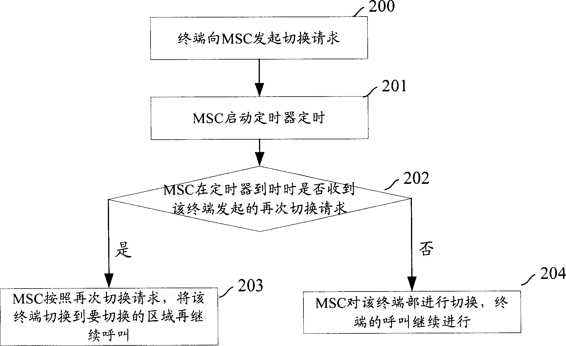
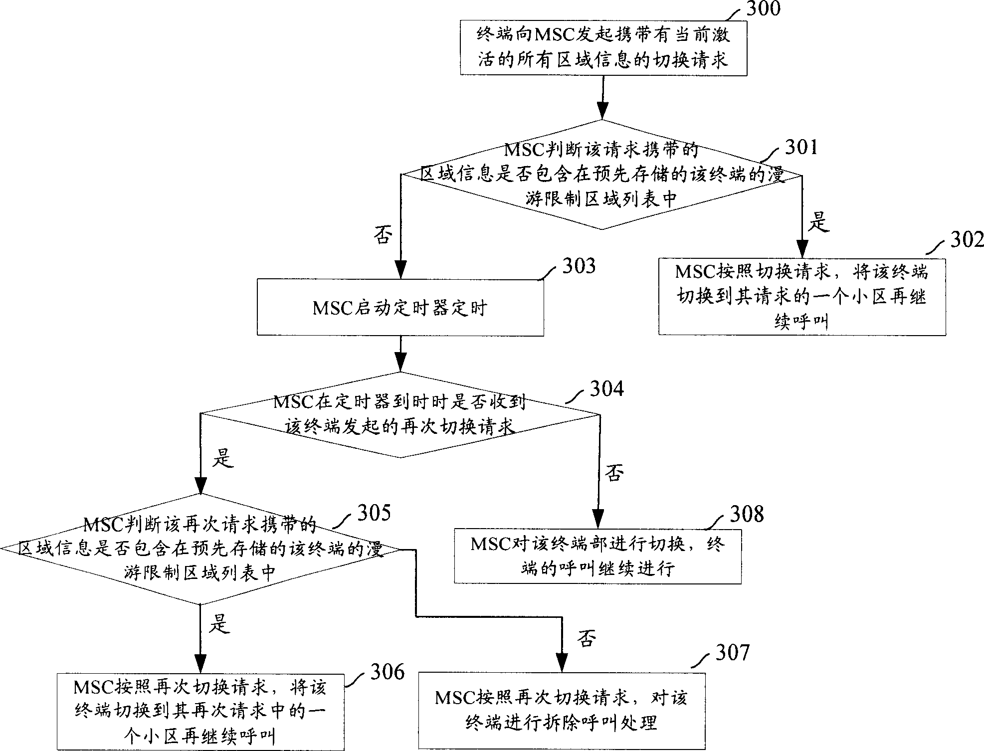
[0029] The core idea of ​​the present invention is: set a timer in advance on the wireless local network network side that governs the terminal, start the timer when the terminal initiates a handover request, and judge whether the terminal initiates a handover request again before the timer expires, and if so, proceed as follows The handover request sent is handed over, and the terminal continues to call after switching to the area to be handed over; otherwise, the handover is not performed, and the call of the terminal continues.

[0030] In the present invention, a timer must be set on the side of the wireless local network that governs the terminal, and the timer can be set in the MSC on the side of the wireless local network that ...


PUM


Abstract

The invention discloses a method by setting timer on local network side to solve terminal repeating switch, which comprises: A. terminal sends switch requirement to local network; B. network side starts timer for timing, and decides whether there is another switch requirement when timing ends; if yes, turns to step C; or else, continues the calling without switch; C. network side switches the terminal to continue calling on switched zone. This invention can avoid frequent switch when calling signal drifts or encounters conflict from other signal, and decreases local network resource.

Description

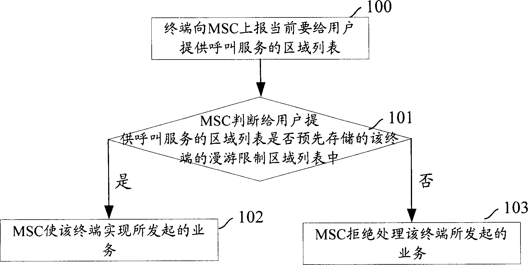
technical field [0001] The invention relates to terminal switching technology in wireless local network, in particular to a method for solving terminal repeated switching. Background technique [0002] At present, there are many wireless local network operators, which have the right to operate wireless local networks, but cannot operate mobile networks. In places with relatively strict regulations, the roaming area of ​​terminals is required not to exceed the area under the jurisdiction of the wireless local network operator. The range of the base station or the range of multiple base stations, beyond the range, the call service cannot be provided to the terminal. This situation is called roaming restriction of the terminal. [0003] Currently, there are many methods to realize roaming restriction judgment of a terminal based on a cell, a single base station or multiple base stations. [0004] figure 1 It is one of the flow charts of the prior art to realize the determina...

Claims


Application Information

Patent Timeline
IPC IPC(8): H04Q7/38H04W36/08
Inventor 唐心红
Owner HUAWEI TECH CO LTD
Learn More