Surface mounting machine

A surface mount machine and a technology for installation, applied in the direction of electrical components, electrical components, etc., can solve the problems of surface mount machine height increase, limited miniaturization, and restriction of the moving range of the adsorption head, and achieve the effect of reducing costs

Active Publication Date: 2006-04-05
YAMAHA MOTOR CO LTD
View PDF3 Cites 10 Cited by
  • Summary
  • Abstract
  • Description
  • Claims
  • Application Information

AI Technical Summary

Problems solved by technology

Therefore, since the rear portion of the above-mentioned tray storage device and the above-mentioned driving motor protrude from the base when viewed from above, the degree of miniaturization is also limited.
[0013] In addition, there is also the following problem: Since the tray storage device is loaded on the base of the surface mounter, the height of the surface mounter equipped with the tray storage device is increased, and the moving range of the suction head is limited by the tray storage device. constraints
That is, this is because, during the period when the tray element is positioned at a predetermined position by the sliding conveying device, the tray element cannot be sucked by the suction nozzle, and the suction head has to be kept on standby during the period.

Method used


Image

  • Surface mounting machine
  • Surface mounting machine
  • Surface mounting machine

Examples


no. 1 Embodiment approach

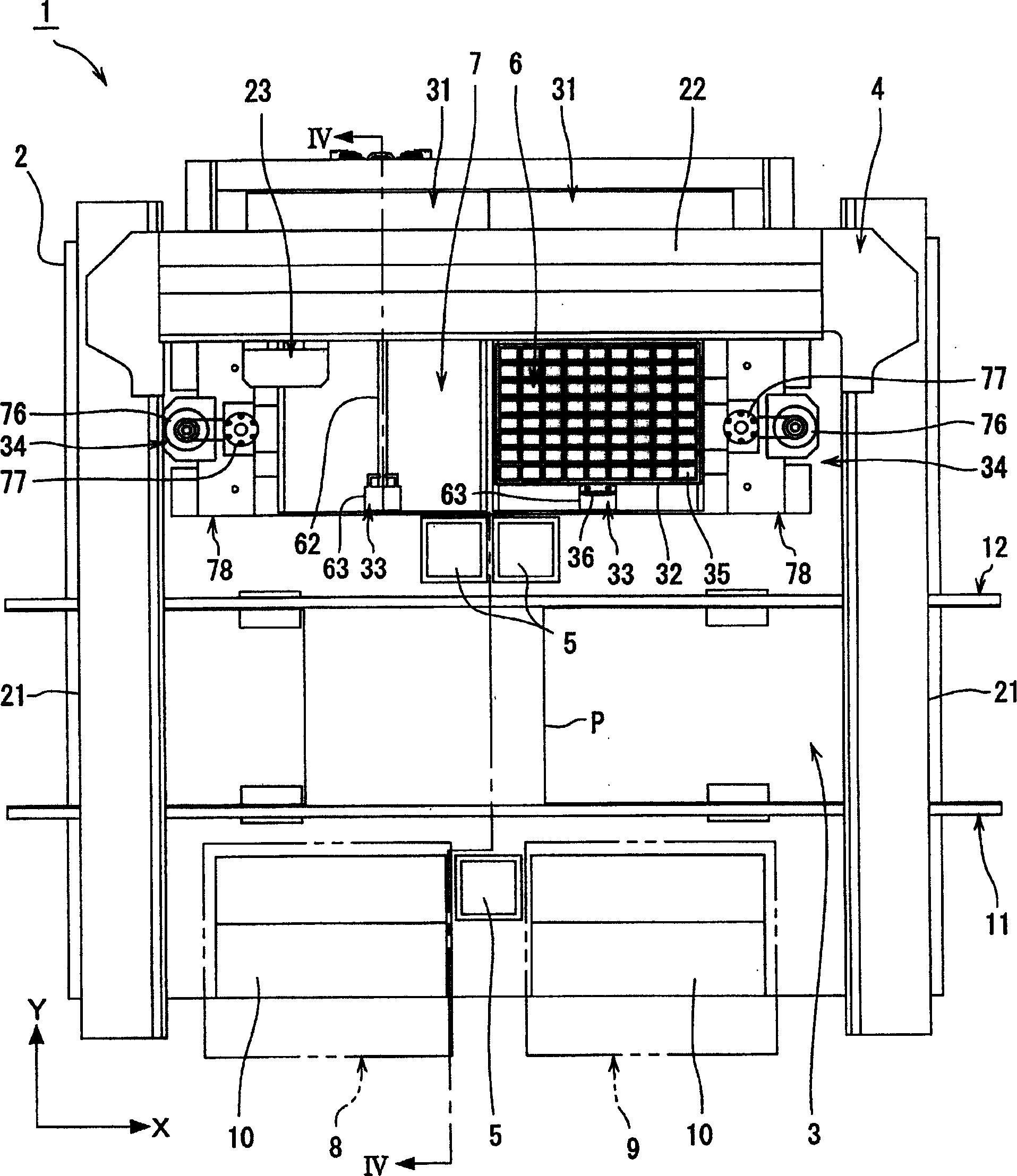
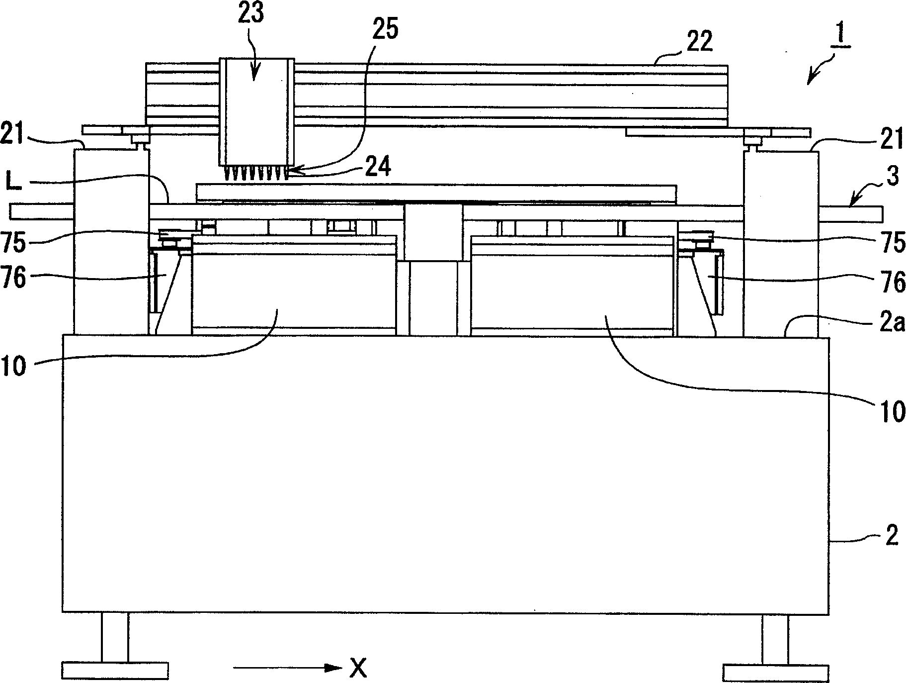
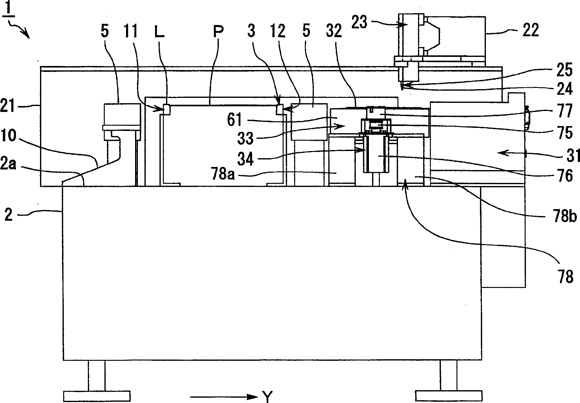
[0060] Use below Figure 1 to Figure 14 One embodiment of the surface mounting machine according to the present invention will be described in detail.

[0061] figure 1 It is a top view of the surface mounting machine involved in the present invention; figure 2 is its front view; image 3 is its side view; Figure 4 is along figure 1 Sectional view of line IV-IV in ; Figure 5 is a perspective view showing the entire surface mounter according to the present invention; Figure 6 is the top view of the tray feeder; Figure 7 is a perspective view of the tray feeder; Figure 8 is an enlarged perspective view showing the upper end of the lifting device; Figure 9 is a perspective view of the pallet entry and exit device; Figure 10 It is a perspective view of the surface mount machine viewed from the back.

[0062] Figure 11 It is a figure showing the lid part when closing the opening and closing member, Figure 11 (A) is a plan view rotated 180° so that the rear sid...

no. 2 Embodiment approach

[0145] Pan feeders can use Figure 17 and Figure 18 structure shown.

[0146] Figure 17 It is a perspective view which shows another embodiment of a pan feeder, Figure 18 It is an enlarged perspective view showing the upper end portion of the lifting device. In these figures, with the above Figure 1 to Figure 16 The same or equivalent parts described in are labeled with the same reference numerals and detailed descriptions are appropriately omitted.

[0147] Figure 17 and Figure 18 The lifter 34 shown is connected to the upper end of the ball screw shaft 72 via a coupling 91 so as to be coaxial with the drive motor 76 . The drive motor 76 is housed in a case 92 and fixed to the support base 78 via the case 92 . An electromagnetic brake 77 for restricting the rotation of the ball screw shaft 72 is provided in the housing 92 . This electromagnetic brake 77 is the same as the electromagnetic brake used in the first embodiment.

[0148] By configuring the elevating...


PUM


Abstract

The invention provides a miniature surface mount machine allocated with a tray-type component feedway. One side of a transporting belt (3) is allocated with a tray-type feeding device (6, 7); the tray-type feeding device (6, 7) consists of a tray (32) used for holding a mount component, a tray holing device (31), a tray in-out device (33) and a lifting device (34). The tray holding device (31) is provided with a plurality of tray holding parts which are used for holding and supporting the tray (32) and can freely go in and go out in the horizontal direction cross with the transporting direction of the transporting belt (3). The tray in-out device (33) leads the tray (32) to do horizontal shift between the holding position in the tray holding parts and the component adsorption position outside the tray holding device (31). The lifting device (34) leads the tray in-out device (33) to lift and descend through a ball screw apparatus which takes the axial direction as the vertical direction. From the overhead view, the tray in-out device (33) and the lifting device (34) are arranged at the inner side of the base (2) of the surface mount machine (1).

Description

technical field [0001] The present invention relates to a surface mounting machine with a pan feeder. Background technique [0002] In the past, as the disc feeder used on the surface mounting machine, as disclosed in the Japanese Patent Application Publication No. 3-133802 or the Publication of the Japanese Patent Application Publication No. 7-336089, it has been proposed to be provided with a plurality of components for loading and mounting components. The tray of the storage unit is accommodated on a tray-shaped tray, and the component supply device supports a plurality of trays side by side in the vertical direction. [0003] The tray feeder shown in Japanese Unexamined Patent Publication No. 3-133802 has a tray accommodating device, stores and supports the trays side by side in the vertical direction, and can freely move in and out in the horizontal direction. The tray storage device is formed separately from the surface mounter, and is arranged side by side on the sid...

Claims


Application Information

Patent Timeline
Patent Type & Authority Applications(China)
IPC IPC(8): H05K13/02H05K13/04
Inventor 大川直尚
Owner YAMAHA MOTOR CO LTD
Why Eureka
Try Eureka