Washing machine and method of controlling the same
A washing machine and water tub technology, applied in the field of washing machines, can solve the problems of easy fire safety hazards, reduced product reliability, reduced drying efficiency, etc., and achieves the effect of enhancing the convenience and stability of use
- Summary
- Abstract
- Description
- Claims
- Application Information
AI Technical Summary
Problems solved by technology
Method used
Image
Examples
no. 1 example
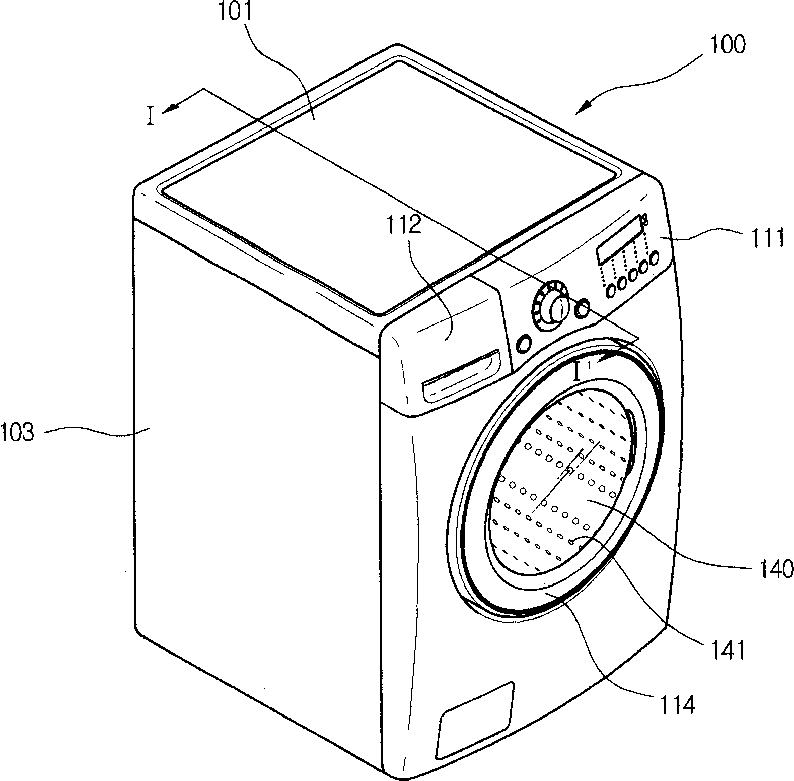
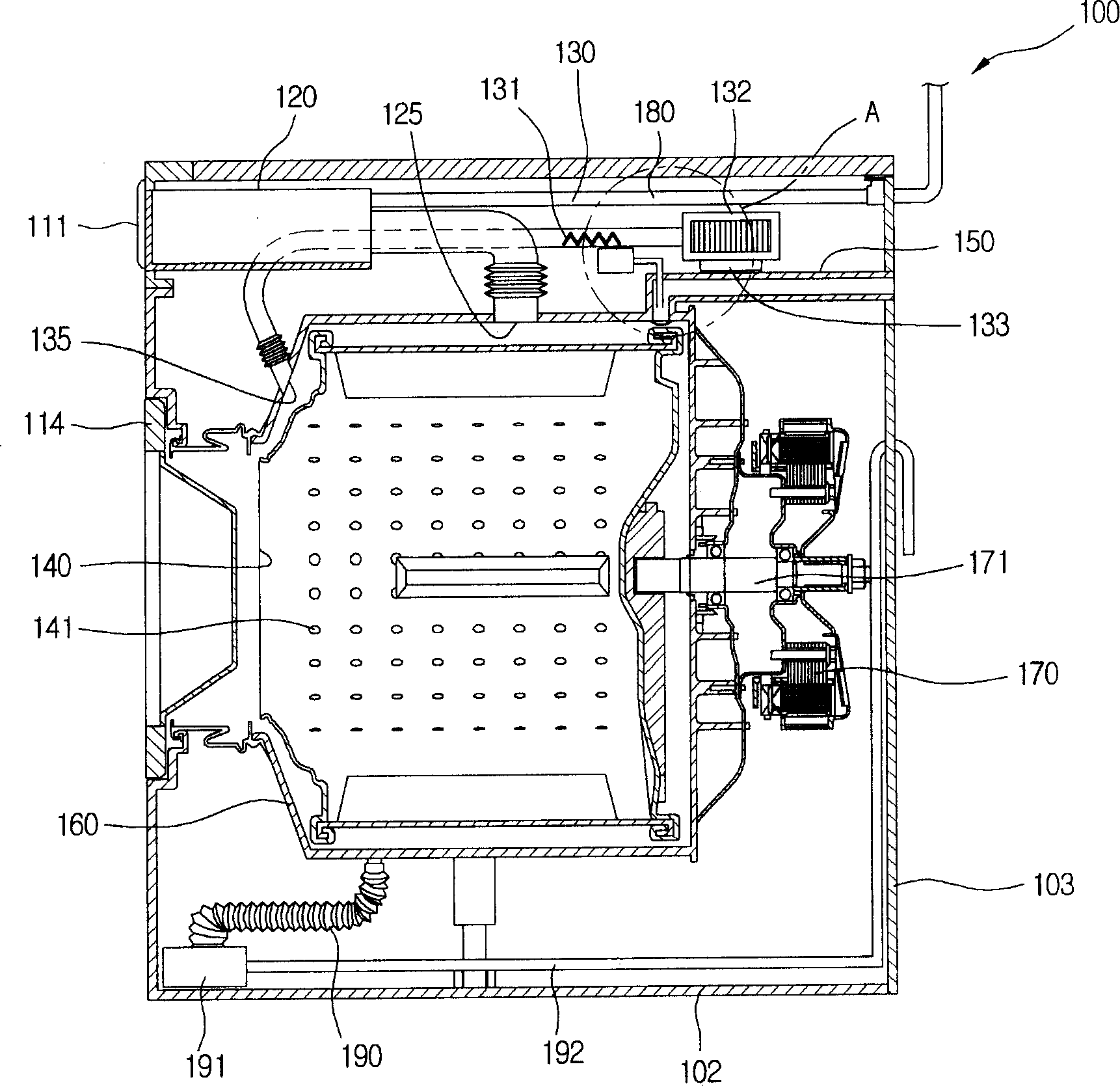
[0034] figure 1 is a schematic diagram of a drum washing machine according to the present invention, figure 2 for along figure 1 The cross-sectional view obtained by the line I-I'.
[0035] refer to figure 1 and figure 2 The main body 100 of the washing machine in which the drum and the tub are installed and the door 114 formed on the front side of the main body 100 constitute the appearance of the washing machine of the present invention. The detergent box 120 and the controller 111 are installed on the upper portion of the main body 100 .
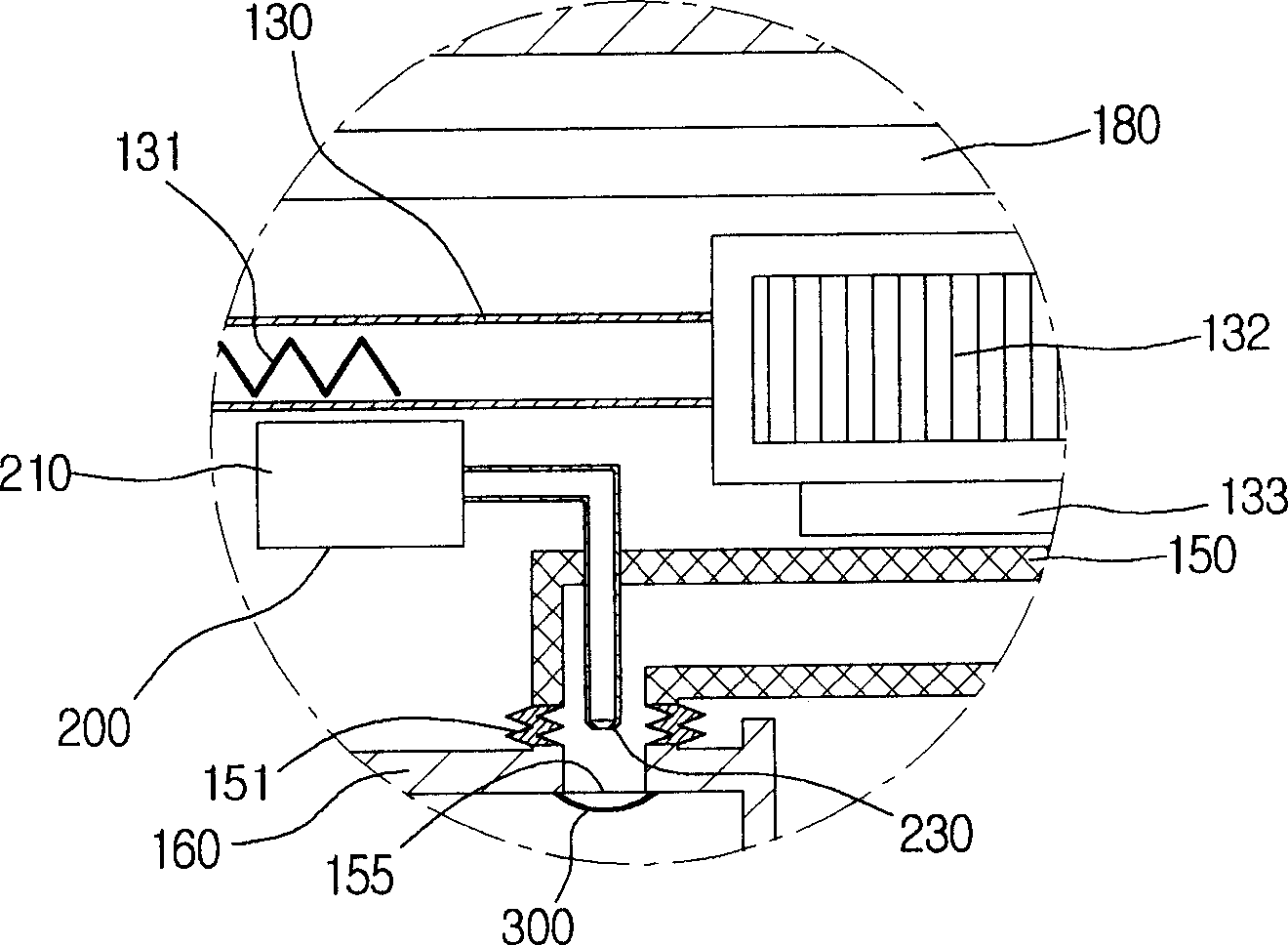
[0036] The main body 100 has a case 103 fixed between the upper plate 101 and the lower plate 102 to form a predetermined space therein. Various components required to operate the washing machine, such as the driving motor 170 and the drum 140, etc., are installed inside the casing 103 of the washing machine. The driving motor 170 rotates the driving shaft 171 using an electric current supplied externally to operate the washing ma...
no. 2 example
[0059] The second embodiment of the present invention is the same as the first embodiment except that the method of spraying air to the filter is different from the first embodiment. Therefore, the difference in the second embodiment will be mainly explained below, and the explanation of the same parts in the first embodiment will be referred to.
[0060] Figure 4 is a sectional view of a washing machine according to a second embodiment of the present invention, Figure 5 Yes Figure 4 Enlarged view of part "B" in .
[0061] refer to Figure 4 and Figure 5 , The lint removing unit 200 has a nozzle 230 connected to the ventilation duct 130, and the ventilation duct 130 has an opening / closing valve 240 for switching the flow direction of the air compressed by the fan 132 therein. The opening / closing valve 240 is installed at the rear side of the connecting portion between the ventilation duct 130 and the nozzle 230 so that the air blown by the fan 132 can flow toward the ...
no. 3 example
[0067] The third embodiment is the same as the second embodiment except that the injection part of the nozzle 230 is different from the second embodiment. Specifically, by distributing the jet of air over a wider area, lint can be removed more effectively.
[0068] Image 6 is a sectional view of a washing machine according to a third embodiment of the present invention, Figure 7 for Image 6 Enlarged view of part "C" in .
[0069] refer to Image 6 and Figure 7 , the nozzle 230 has a discharge end including at least one branch toward the entire rear surface of the filter 300 . Since the nozzle 230 is branched as described above, compressed air is sprayed to the entire surface of the filter 300 . Therefore, it is possible to effectively remove the lint accumulated on the entire surface of the filter 300 .
[0070] This solution can be directly applied to the first embodiment.
PUM
 Abstract
Description
Claims
Application Information
 - R&D
- Intellectual Property
- Life Sciences
- Materials
- Tech Scout
- Unparalleled Data Quality
- Higher Quality Content
- 60% Fewer Hallucinations
Browse by: Latest US Patents, China's latest patents, Technical Efficacy Thesaurus, Application Domain, Technology Topic, Popular Technical Reports.
© 2025 PatSnap. All rights reserved.Legal|Privacy policy|Modern Slavery Act Transparency Statement|Sitemap|About US| Contact US: help@patsnap.com


