Method for guiding band into a rewinder and rewinder thereof

A technology of rewinding machine and strip, applied in the field of rewinding machine, can solve problems such as difficulty in automatic operation and errors, and achieve the effect of simplifying the threading and guiding of strips

Inactive Publication Date: 2006-04-19
VOITH PATENT GMBH
View PDF2 Cites 18 Cited by
  • Summary
  • Abstract
  • Description
  • Claims
  • Application Information

AI Technical Summary

Problems solved by technology

This monitoring can lead to additional errors, making automation difficult

Method used


Image

  • Method for guiding band into a rewinder and rewinder thereof
  • Method for guiding band into a rewinder and rewinder thereof

Examples


Embodiment Construction

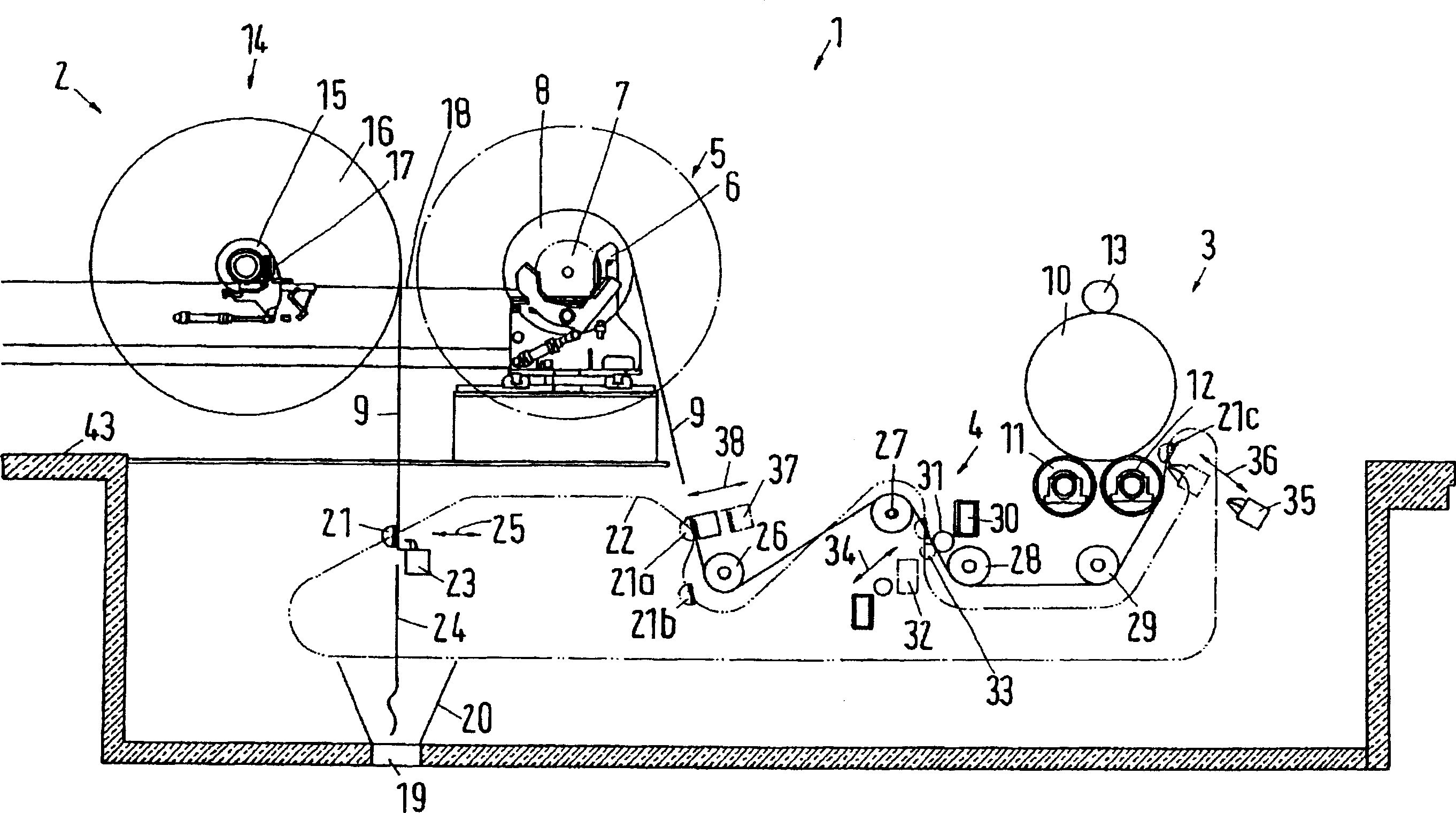
[0036] figure 1 is a schematic diagram of a rewinder 1 with an unwinding station 2 and a winding station 3 . The slitter 4 is arranged between the unwinding station 2 and the winding station 3 .

[0037] There is an unfolding position 5 in the unfolding station. In the unfolded position 5 there is an unfolding bearing 6 on which a reel 7 is rotatably mounted. The original tape roll 8 is wound on the reel 7, from figure 1 Part of it can also be seen. The strip 9 is drawn from the original coil 8, which may also be called a "jumbo coil". The strip 9 is cut into a plurality of strip sections at the slitter 4 and wound into a plurality of rolls 10 at the winding station 3, since these rolls 10 are arranged in a direction perpendicular to the plane of the drawing. pick one, so in figure 1 Only one roll is visible in .

[0038] The unrolling bearing 6 is suitable for relatively high speed operation. For example, the strip 9 may be withdrawn at a speed of 2000 to 3000 m / min. ...


PUM


Abstract

The procedure involves supplying of material coil (9), which is taken off from supply roller in full width by means of an auxiliary device (21), in winding position (12). The auxiliary device is detached from the material coil in the area of winding position. An independent claim is also included for the roller winding device.

Description

technical field [0001] The invention relates to a method of threading a material web into a rewinder, wherein the starting end of the web is pulled from a supply roll in full width by means of auxiliary means. Furthermore, the invention relates to a rewinding machine with an unwinding station having at least one position for supplying a coil and a winding station having at least one winding position and auxiliary devices , the auxiliary device clamps the strip from the supply roll at full width in the area of ​​the unwinding station. Background technique [0002] A method and rewinder of this type are disclosed in EP0820946B1. In order to facilitate winding of the strip, the strip, after being drawn on the supply roll, is guided onto a cutting device which cuts points from the strip. For this purpose, the rewinder has at least one knife which is movable transversely with respect to the direction of movement of the strip as it passes. In this way, the strip can be cut at a...

Claims


Application Information

Patent Timeline
Patent Type & Authority Applications(China)
IPC IPC(8): B65H19/28B65H20/00B65H35/02B65H18/08B65H16/00
CPCB65H2301/4148B65H19/28B65H2301/522B65H2801/84B65H2301/41734
Inventor 赫尔曼·A·斯蒂茨约瑟夫·内利斯安德烈亚斯·科罗奈
Owner VOITH PATENT GMBH
Why Eureka
Try Eureka