
Fabric presser of sewing machine

A sewing machine and medium pressure technology, which is applied to the sewing machine control device, sewing machine components, and program-controlled sewing machines, etc., can solve the problems such as the inability to maintain the height of the intermediate presser foot, the large stroke of the intermediate presser foot, and the change.

Active Publication Date: 2006-04-19
JUKI CORP
View PDF2 Cites 2 Cited by
  • Summary
  • Abstract
  • Description
  • Claims
  • Application Information

AI Technical Summary

Problems solved by technology

[0007] However, in Patent Document 1, when the height of the intermediate presser is changed by displacing the swing center, the stroke of the intermediate presser also changes greatly.
In addition, in order to raise the intermediate presser to the retracted position, a considerable amount of displacement of the swing center is required, so the face of the sewing machine is enlarged.
Furthermore, if the swing center is not adjusted as the intermediate presser stroke is adjusted, the height of the intermediate presser cannot be kept constant.
[0008] In Patent Document 2, when the cam is rotated to change the inclination of the connecting rod to change the height of the intermediate presser foot from the needle plate, if there is a height difference in the material, the oscillating body and the cam repeatedly come into contact with and separate from each other. Mutual abutment surfaces are easily damaged

Method used


Image

  • Fabric presser of sewing machine
  • Fabric presser of sewing machine
  • Fabric presser of sewing machine

Examples


Embodiment 1

[0053]

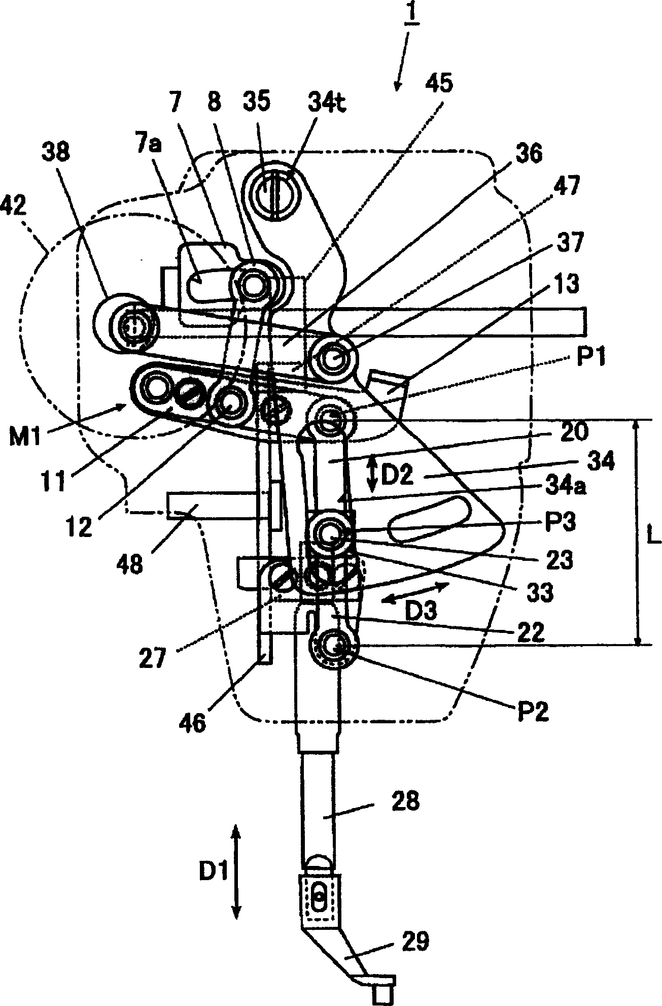
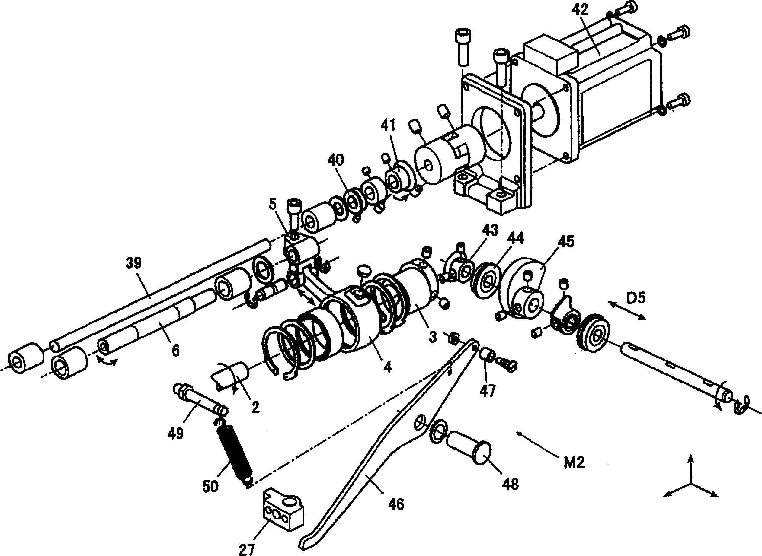
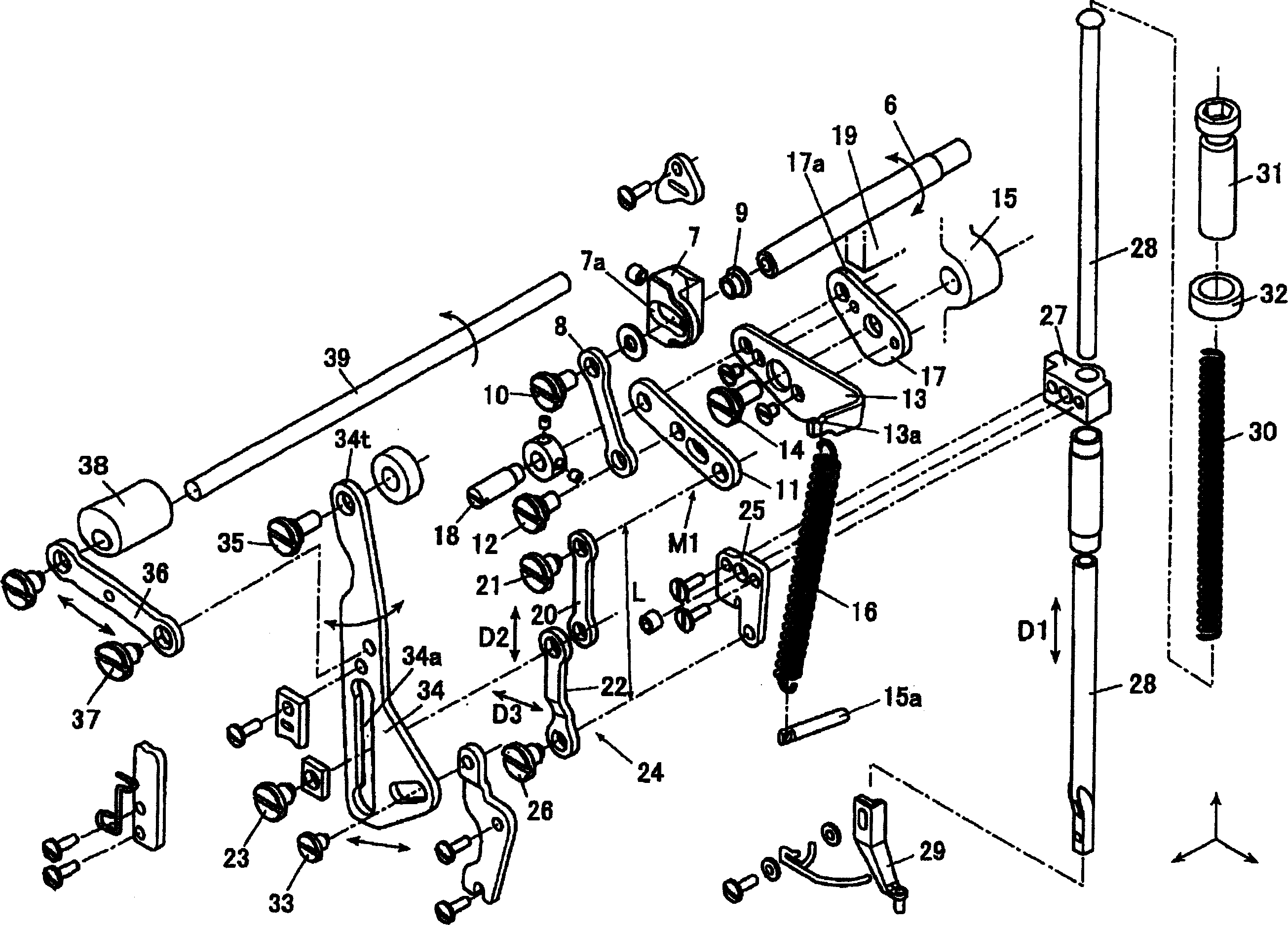
[0054] Such as Figure 1 ~ Figure 3 As shown, the middle cloth pressing device 1 is arranged on the upper shaft 2, and the upper shaft 2 drives the needle bar provided with the machine needle at the front end to move in the up and down direction. The eccentric cam 3 is fixed on the upper shaft 2, and the connecting link 4 is connected on the eccentric cam 3. The rocking shaft abutment 5 is connected to the connecting rod 4 , and one end of the rocking shaft 6 is connected to the rocking shaft abutment 5 .

[0055] At the other end of the rocking shaft 6, a base end portion of an intermediate presser adjusting arm 7 for adjusting the movement amount of the intermediate presser in the vertical direction D1 is fixed. A grooved cam 7 a is formed on the intermediate presser adjusting arm 7 . The grooved cam 7a is an arc-shaped long hole, and the desired position of the grooved cam 7a and one end of the first link 8 are rotatably fixed by the adjusting nut 9 and the seg...

Embodiment 2

[0094]

[0095] The intermediate cloth pressing device 1G of the second embodiment can retract the intermediate presser foot 29 to the retracted height position P5 with a smaller force than that of the first embodiment. In addition, in the middle cloth pressing device 1G, the moving link 36 is changed to a moving mechanism 51, and this moving mechanism 51 also functions as a releasing mechanism for releasing the elastic force applied to the second link 11 by the coil spring 16. Regarding other parts , since they have the same configuration as in Embodiment 1, they are marked with the same symbols and descriptions thereof are omitted.

[0096] Such as Figure 9 As shown, the moving mechanism 51 has a rotating link 52 whose one end is connected to the movable shaft 39 , and an adjustment mechanism whose one end is connected to the other end of the rotating link 52 and the other end is connected to the guide member 55 . Connecting rod 53.

[0097] The adjustment link 53 has o...


PUM


Abstract

The invention adjusts the height of a center presser from a needle plate without changing the stroke of the center presser. The center presser has a guide member 34 forming a center presser link member 24 by connecting two links 20 and 22 in series, making a connecting portion P3 to connect the links movable in the series direction D2 of the links 20 and 22 and regulating a movement in the direction D3 intersecting the series direction D2 of the links 20 and 22, a movement means 36 to move the guide member 34 in the crossing direction D3 to the series direction D2 of the links, and a driving means 41 to drive the movement means 36.

Description

technical field [0001] The invention relates to a middle cloth pressing device of a sewing machine. Background technique [0002] Conventionally, in sewing machines such as embroidery sewing machines, which transport the material in the XY direction without using the feed dog and sew, in order to prevent the sewing confusion caused by the friction between the material and the needle, which causes the material and the needle to rise together, a Intermediate fabric presser device that presses the fabric around the needle penetration part downward when the needle is raised. This device usually presses the cloth downwards by the middle presser foot when the machine needle rises from the cloth, and after the machine needle completely rises from the cloth, the middle presser foot and the machine needle rise together. [0003] As such an intermediate cloth pressing device, an intermediate cloth pressing device capable of adjusting the height of the intermediate presser foot from t...

Claims


Application Information

Patent Timeline
IPC IPC(8): D05B29/02
CPCD05B19/12D05B29/02D05B29/08D05B69/02D05B69/30
Inventor 坂井克秋三须伸介
Owner JUKI CORP
Learn More