
Plasma display apparatus

A plasma and display device technology, which is applied to alternating current plasma display panels, identification devices, solid cathode components, etc., can solve the problems of base plate manufacturing and its complex structure, and achieve the effect of maintaining flatness and being easy to assemble and disassemble

Inactive Publication Date: 2006-04-19
SAMSUNG SDI CO LTD
View PDF0 Cites 2 Cited by
  • Summary
  • Abstract
  • Description
  • Claims
  • Application Information

AI Technical Summary

Problems solved by technology

As a result, the manufacture of the base plate and its structure are complicated

Method used


Image

  • Plasma display apparatus
  • Plasma display apparatus
  • Plasma display apparatus

Examples


Embodiment Construction

[0035] Hereinafter, exemplary embodiments of the present invention will be described in detail with reference to the drawings.

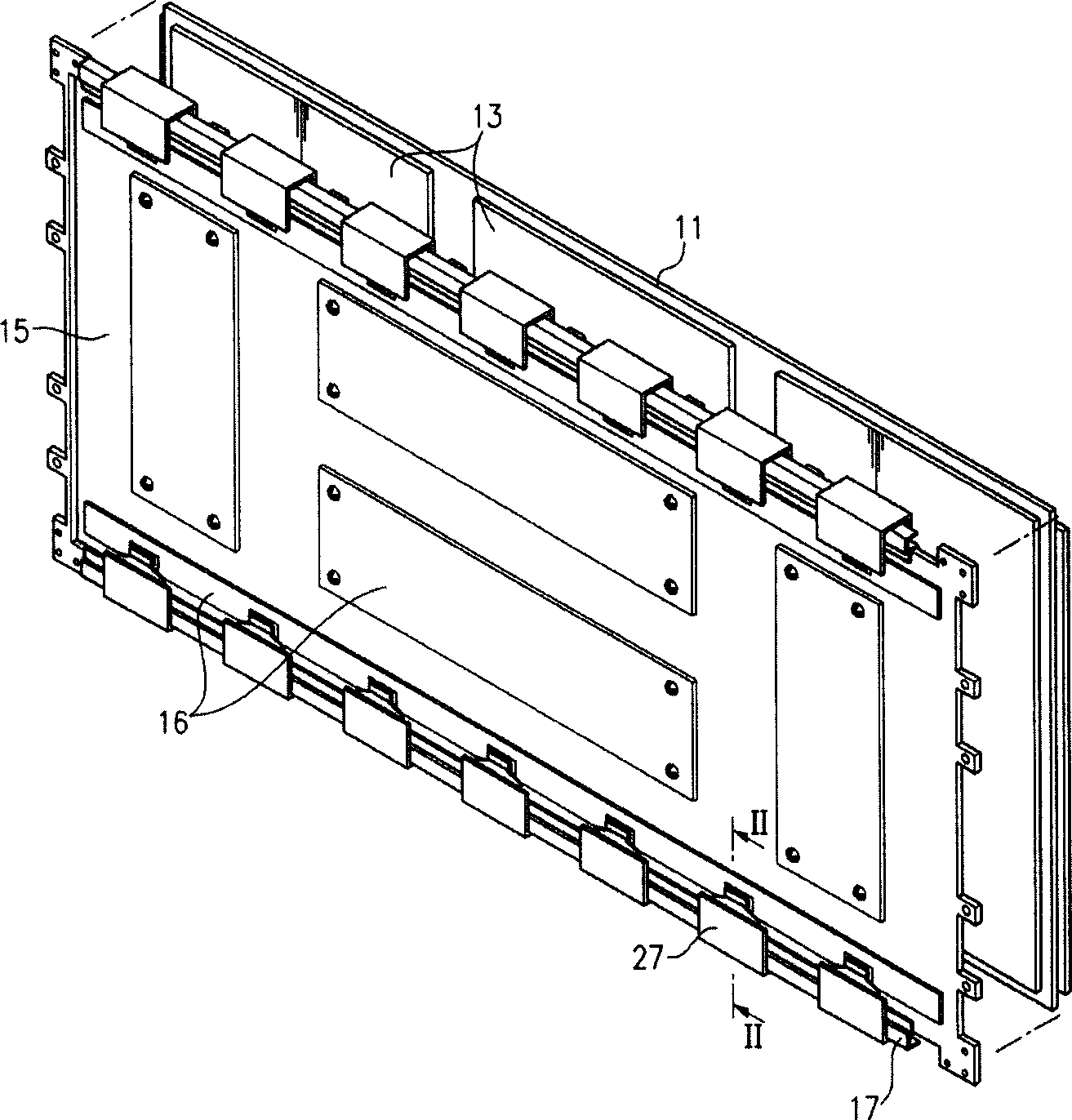
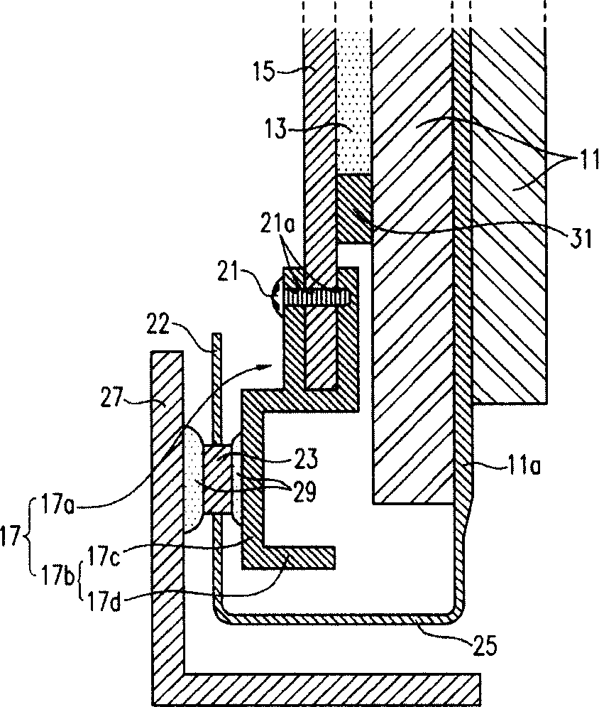
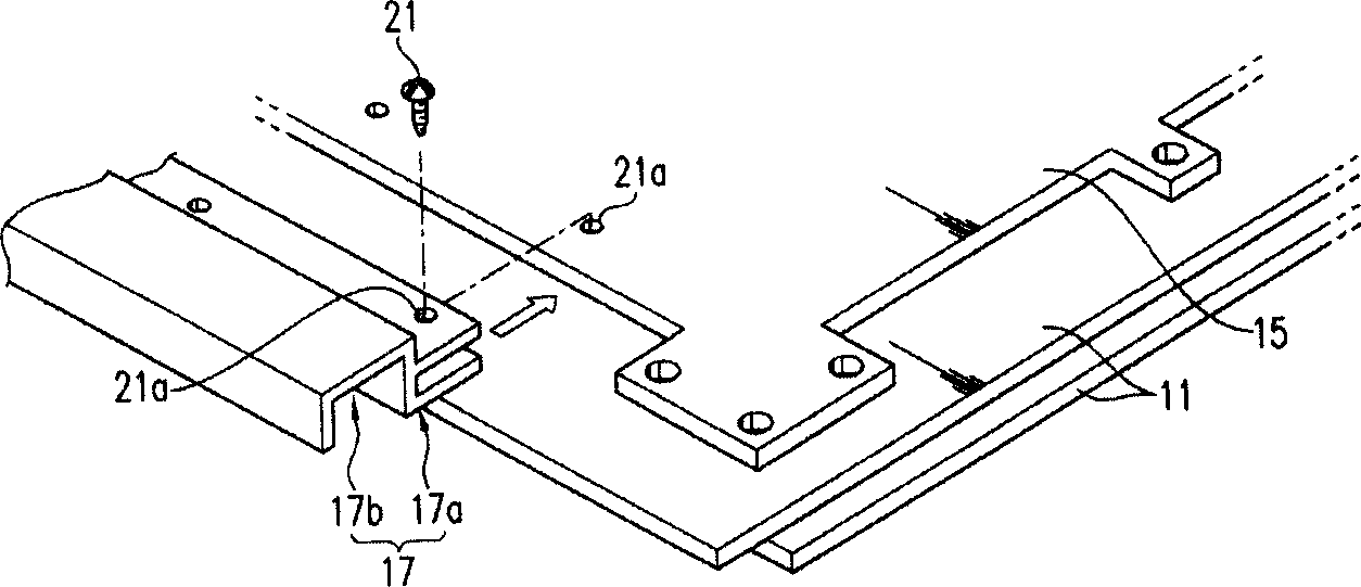
[0036] figure 1 is an exploded perspective view of a plasma display device according to a first exemplary embodiment of the present invention, figure 2 is along figure 1 A cross-sectional view of the assembled plasma display device taken along line II-II, image 3 is a partial perspective view of the first exemplary embodiment in which the reinforcing unit has been removed from the base plate.

[0037] The plasma display device includes a PDP 11 that displays images using gas discharge, and the PDP 11 has a front surface and a rear surface. A heat conduction sheet 13 is attached to the rear surface of the PDP 11 . In the PDP, gas discharge generates heat, and the thermally conductive sheet 13 dissipates heat in the plane direction of the PDP 11 . The plasma display device also includes a bottom plate 15 attached to the rear surface of the PDP 1...


PUM


Abstract

A plasma display apparatus includes a Plasma Display Panel (PDP). A thermal conductive sheet is attached to one side of the PDP, and a chassis base is connected to the side of the PDP on which the thermal conductive sheet has been attached. The chassis base can be a planar plate having edge portions. At least one reinforcing unit is extends along and is attached to at least one of the edge portions of the chassis base.

Description

technical field [0001] The invention relates to a plasma display device. More particularly, the present invention relates to a plasma display device in which a chassis of the plasma display device is capable of resisting bending and twisting loads so as to maintain its flatness, wherein the chassis and plasma display panel (PDP) are easily implemented. assembly and disassembly. Background technique [0002] A plasma display device comprising: a plasma display panel (PDP) displaying images using plasma generated by gas discharge; a base plate supporting the PDP; and a circuit board assembly mounted on one side of the base plate opposite to the side adjacent to the PDP on the side. The circuit board assembly is electrically connected to display electrodes and address electrodes within the PDP through a flexible printed circuit (FPC), a connector, or a tape carrier package (TCP). [0003] A PDP includes two glass substrates sealed together opposite e...

Claims


Application Information

Patent Timeline
Patent Type & Authority Applications(China)
IPC IPC(8): G09F9/313H01J17/16H01J11/10H01J17/28
CPCH01J11/20H01J11/34H01J17/16H01J17/28H01J2211/66H01J2217/492H05K7/20963
Inventor 金基正
Owner SAMSUNG SDI CO LTD
Features
  • Generate Ideas
  • Intellectual Property
  • Life Sciences
  • Materials
  • Tech Scout
  • Unparalleled Data Quality
  • Higher Quality Content
  • 60% Fewer Hallucinations
Learn More