Networked video moniotring and controlling system in operation level

A network video monitoring, operation-level technology, applied in the direction of closed-circuit television systems, etc., can solve the problems of inconvenient unified management, inability to realize multi-level platform interconnection, and inability to perform unified resource scheduling, so as to achieve the effect of interconnection

Inactive Publication Date: 2006-04-19
CHINA TELECOM CORP LTD
View PDF0 Cites 40 Cited by
  • Summary
  • Abstract
  • Description
  • Claims
  • Application Information

AI Technical Summary

Problems solved by technology

[0006] Although the network video monitoring system solves the problem of remote image viewing and control, it is not suitable as an operation-level product. The main reason is that the communication standards adopted by the encoders of the front-end equipment are chaotic, and it is impossible to achieve unified access to the platform; the platform communication standard Chaos, unable to realize multi-level platform interconnection, unable to perform unified resource scheduling
Each monitoring system is like a solitary boat, and unified management is extremely inconvenient

Method used


Image

  • Networked video moniotring and controlling system in operation level
  • Networked video moniotring and controlling system in operation level
  • Networked video moniotring and controlling system in operation level

Examples


Embodiment Construction

[0027] The following is based on Figure 1 to Figure 6 A preferred embodiment of the present invention is given, and the technical details of the present invention are further provided and described in detail so as to make it easier to understand the structural features and functional characteristics of the present invention, but it is not intended to limit the scope of the present invention.

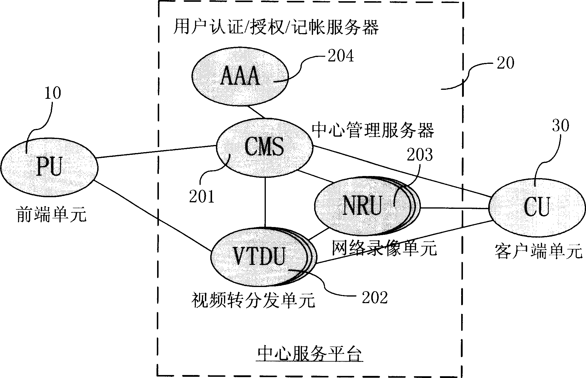
[0028] see figure 1 , which shows the physical architecture of a network video surveillance system. As shown in the figure, it includes a front-end unit 10, a client unit 30, and a central service platform 20, including: a central management server 201, a video forwarding and distribution unit 202, a network video recording unit 203, and a user authentication / authorization / accounting server 204. All the above parts are connected to the IP bearer network, in which:

[0029] 1. The front-end unit 10 (PU), which is responsible for collecting, caching, encoding, storing and sending audio ...


PUM


Abstract

Physical architecture of the system includes front-end unit connected to IP load carrying network, client end units and central service platform. The platform is composed of central management server, authentication / authority / charging servers, video forwarding and distributing unit, and network image recording unit. Characters are that the physical architecture is divided into the operation support layer, the media exchange layer, and the user access layer. The central service platform, front-end unit and client end units constitute an edge domain, and multiple edge domains are managed by a management center in upper level so as to form a domain in second level. Analogically, a domain in third level is formed in tree structure, which is defined as architecture of provincial and nationwide management center as well as operation and support layer of edge domain on the dedicated IP network. Devices are on the IP network and front-end units and client end units are connected to the devices.

Description

technical field [0001] The invention relates to a system for video monitoring and network image management, in particular to a large-scale operation-level network video monitoring system based on embedded and video technology, and based on a network and communication technology platform. Background technique [0002] The development of network video surveillance technology, for example, has gone through the following three stages in China: [0003] 1. Early closed-circuit video surveillance system. It evolved from security products and is the first generation of analog video surveillance system. [0004] 2. The PC-based plug-in video surveillance system began in the mid-1990s. Although digitalization has been initially realized, the second-generation video surveillance system is still only used as a security product for daily monitoring in certain industries due to technical deficiencies such as image quality, stability, and remote transmission monitoring. [0005] 3. The...

Claims


Application Information

Patent Timeline
Patent Type & Authority Applications(China)
IPC IPC(8): H04N7/18
Inventor 冯明雍丽苹郑泽民曹宁李杰梁笃国熊静冯传滨
Owner CHINA TELECOM CORP LTD
Why Eureka
Try Eureka