
Reconfigurable logical circuit using transistor having spin-dependent transmission characteristics

一种自旋晶体管、转移特性的技术,应用在逻辑电路领域,能够解决不能非易失地存储等问题

Inactive Publication Date: 2006-04-26
JAPAN SCI & TECH CORP
View PDF0 Cites 10 Cited by
  • Summary
  • Abstract
  • Description
  • Claims
  • Application Information

AI Technical Summary

Problems solved by technology

In addition, since the function cannot be stored non-volatilely, there is a problem in maintaining the non-volatileness of the logic function similarly to the LUT method

Method used


Image

  • Reconfigurable logical circuit using transistor having spin-dependent transmission characteristics
  • Reconfigurable logical circuit using transistor having spin-dependent transmission characteristics
  • Reconfigurable logical circuit using transistor having spin-dependent transmission characteristics

Examples


Embodiment Construction

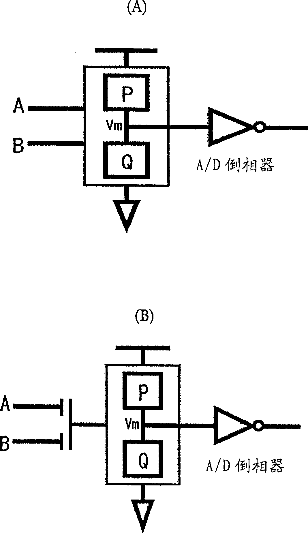
[0078] First, refer to figure 1 (A), (B) The basic structure of the circuit of this invention is demonstrated. like figure 1 Shown in (A), (B), the circuit of the present invention takes the following components as main structural factors: terminal V m (Hereafter, also use "V m "As the terminal name, but sometimes also used as its potential); for the terminal V m The circuit group P for charging the parasitic capacitance in and the input capacitance of the next stage; the circuit group Q for discharging; and the analog voltage V m A / D converter that amplifies to digital logic level. V m It is determined by the values ​​of the input signals A and B, and is determined independently of the next-stage circuit.

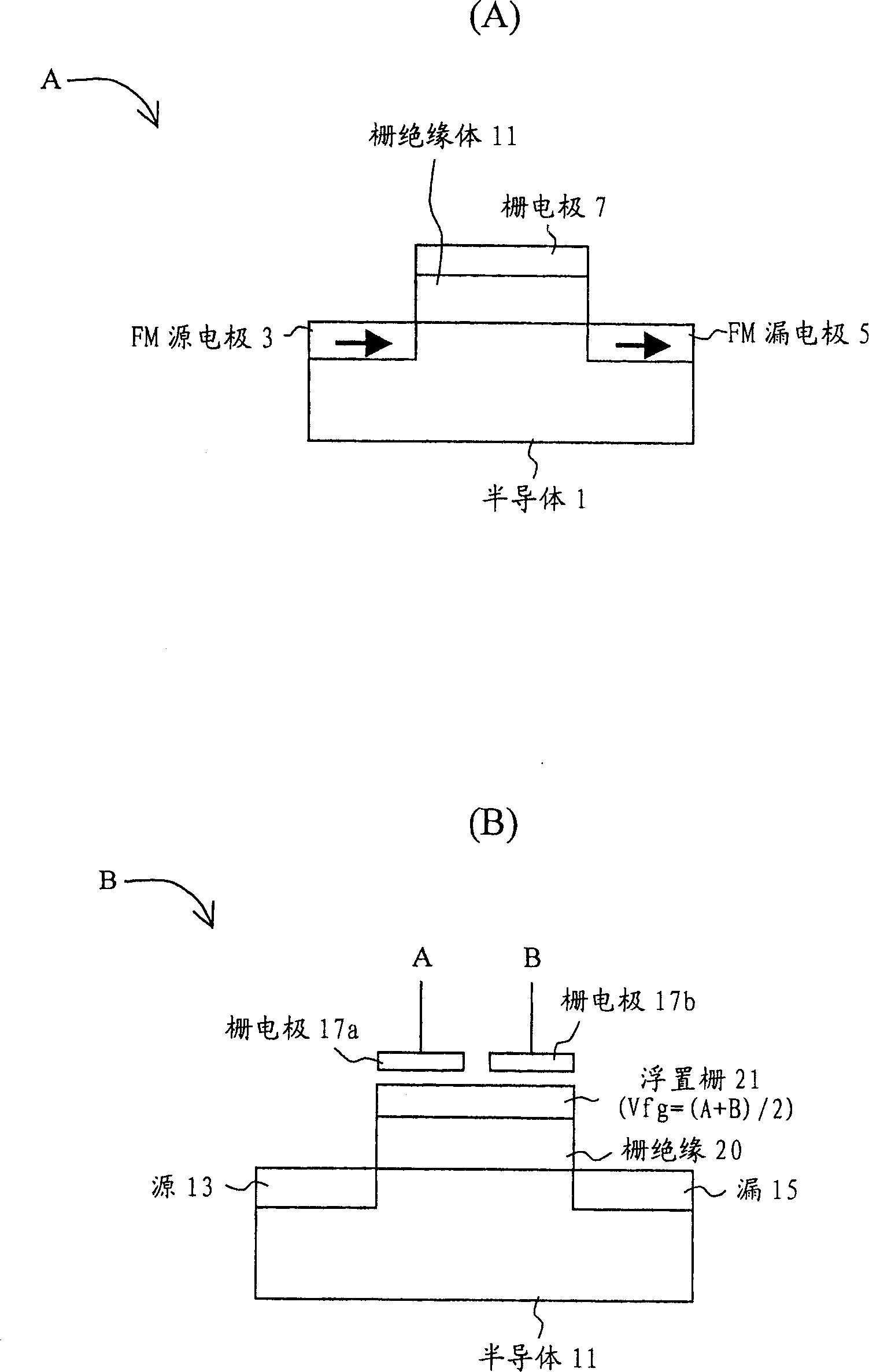
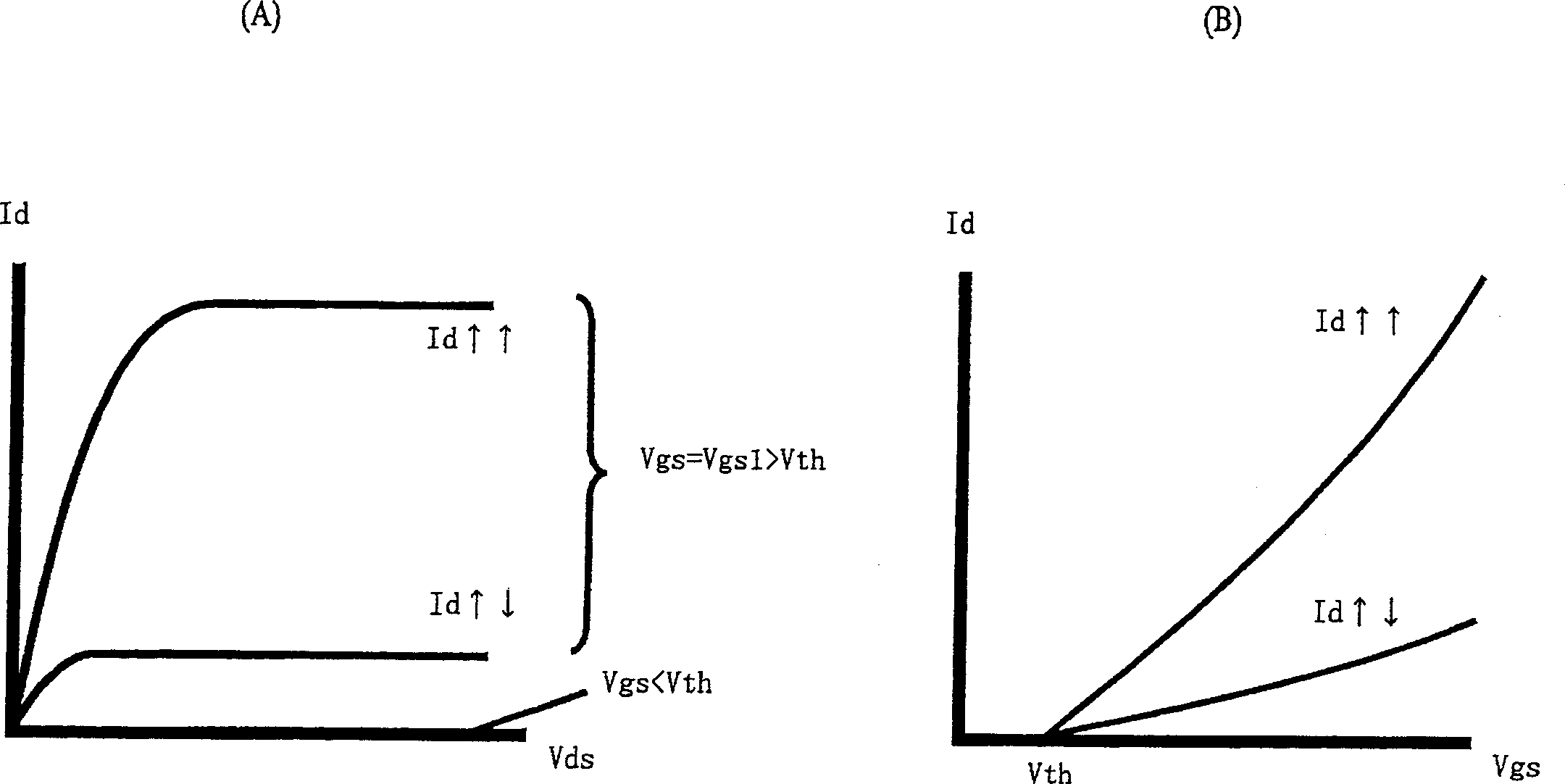
[0079] like figure 1 As shown in (A), at least one of the circuit group P and the circuit group Q includes a spin transistor, and the current drive capability can be controlled by the magnetization state of the spin transistor. Therefore, even if the inputs A an...


PUM


Abstract

The object of the present invention is to construct a nonvolatile reconfigurable logic circuit. This is a reconfigurable logic circuit using a CMOS structure of spin MOSFETs. By changing the transfer characteristics of each transistor by the magnetization states of Tr1, Tr2, Tr5, and Tr8 as spin-NOSFETs, "and" / "or" / "exclusive" / "and" / "or" / " Same as " / "1" / "0" full 2-input symmetric function. Since logic functions can be configured in a non-volatile manner with a small number of components, the chip area can be reduced, and high-speed and low-power consumption operation is expected.

Description

technical field [0001] The present invention relates to a logic circuit whose function can be reconfigured, and more specifically, relates to a transistor (hereinafter referred to as a transistor) using a ferromagnetic substance inside and having transfer characteristics related to the magnetization state of the ferromagnetic substance. A reconfigurable logic circuit called a "spin transistor"). Background technique [0002] In recent years, a logic circuit whose function can be reconfigured (reconfigurable or reprogrammable) by a user's program has attracted attention. For example, the field programmable logic array (Field Programmable Logic Array (FPGA)) (for example, refer to S.Trimberger, Proc.IEEE 81 (1993) 1030., S.Hauck, Proc. .IEEE 86(1998)625., and Minoru Sue: Programmable Logic Devices, Technical Research Report of the Society of Electronics, Information and Communication, Vol.101, No.633, (2002)17). In the past, FPGAs have been used for trial production of produ...

Claims


Application Information

Patent Timeline
Patent Type & Authority Applications(China)
IPC IPC(8): H03K19/20H01L29/66H03K19/0944
CPCH01L29/66984H03K19/0944H03K19/20
Inventor 菅原聪松野知纮田中雅明
Owner JAPAN SCI & TECH CORP
Learn More