
Retraction type safety syringe

A technology for safe injection and injection needles, which is applied in the field of retractable safe injection syringes, and can solve the problems of not having to replace the injection needles, being unable to achieve a wide range of applications, and having no safe retraction and storage of the injection needles.

Inactive Publication Date: 2006-05-03
INTAI TECH CORP
View PDF0 Cites 6 Cited by
  • Summary
  • Abstract
  • Description
  • Claims
  • Application Information

AI Technical Summary

Problems solved by technology

[0004] Since the outer cylinder, protruding small tube or spiral tube of the traditional injection syringe are all integrated, the injection needle has no function of safe retraction and storage. In order to solve this problem, a special retraction needle has been developed in recent years. Type safety injection syringe, which is mainly composed of an outer cylinder combined with a reciprocating push rod, and the inner cavity of the outer cylinder is directly connected to a special injection needle specially made at the front end. When the push rod is displaced to the end of the stroke in the direction of the injection needle, the front end of the push rod and the special injection needle can make the push rod engage with the special injection needle. At this time, pull the push rod backward , that is, to guide the displacement of the special injection needle into the inner cavity of the outer cylinder, so that when the injection operation is completed, the special injection needle can be retracted into the inner cavity of the outer cylinder, thereby preventing the injection needle from being exposed to the outside However, since the retractable safety syringe of the special injection needle does not have the function of replacing the injection needle, it will cause safety, sanitation and inconvenient operation concerns in practice.
[0005] In addition, the retractable safety syringe of the special injection needle is only suitable for its specially made special injection needle, so it cannot achieve the effect of wide application, so further research and improvement are necessary

Method used


Image

  • Retraction type safety syringe
  • Retraction type safety syringe
  • Retraction type safety syringe

Examples


Embodiment Construction

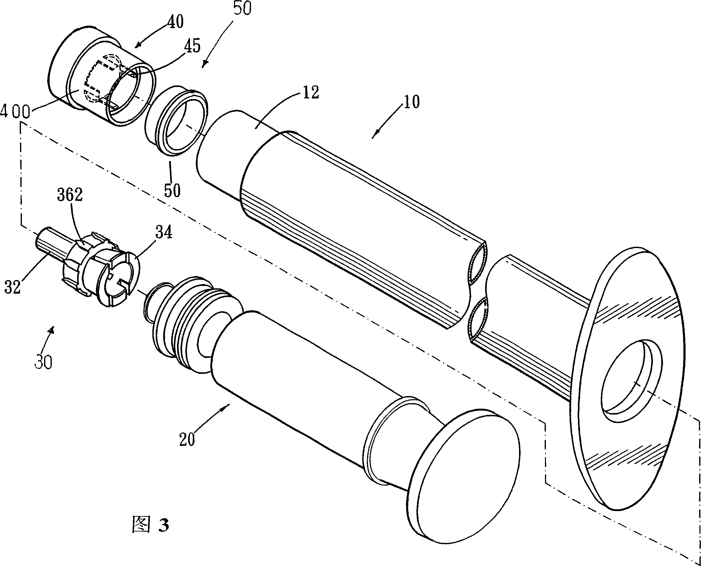
[0027] Please refer to Figures 3 to 6, the retractable safety injection syringe of the present invention mainly includes an outer cylinder 10, a cap sleeve 40, a connecting seat 30, a push rod 20 and an injection needle 90, wherein the outer cylinder 10 is a hollow tube, and the inner cavity of the outer cylinder 10 protrudes radially near the front end to form a protruding ring 13 , so that the inner cavity of the outer cylinder 10 forms a front cavity 12 and a rear cavity 14 .

[0028] The cover sleeve 40 is a tubular body formed by thermal fusion bonding of the cylinder body 400 and the sealing ring 50, and is tightly fitted in the front chamber 12; The anterior cavity 12 of the front cavity is an interference fit for fixing the cap sleeve 40; the sealing ring 50 is a tubular body formed from an elastic material (such as rubber), and the outer circumference of the sealing ring 50 is connected to the outer cylinder 10 The close fit of the inner wall of the front chamber 12 f...


PUM


Abstract

The invention provides a whip-back safe syringe comprising an outer cylinder, a top cap muffle, a connection base, a push bar and an injection needle. Wherein, the front end of said outer cylinder is sheathed with the top cap muffle; the inner chamber of top cap muffle is sheathed to the connection base which is connected to the injection needle; the push bar is in the inner chamber of said outer cylinder for abstracting the injection or injecting and drawing said connection base; the inner wall of said top cap muffle has double thread while its another end via heat fuse is connected to a sealed ring; the connection base comprises a concave small pipe and the main body of base, which is arranged inside said top cap muffle and the main body of base has a device clamped with push bar to draw the connection base back into the outer cylinder. The invention can make the connection base and injection needle back into the chamber of outer cylinder, to realize the safe protection and the reliability of anti-leak of injection. In addition, the invention integrates the top cap muffle and connection base both of which are slipped into the front end of outer cylinder to improve the convenience of assembly.

Description

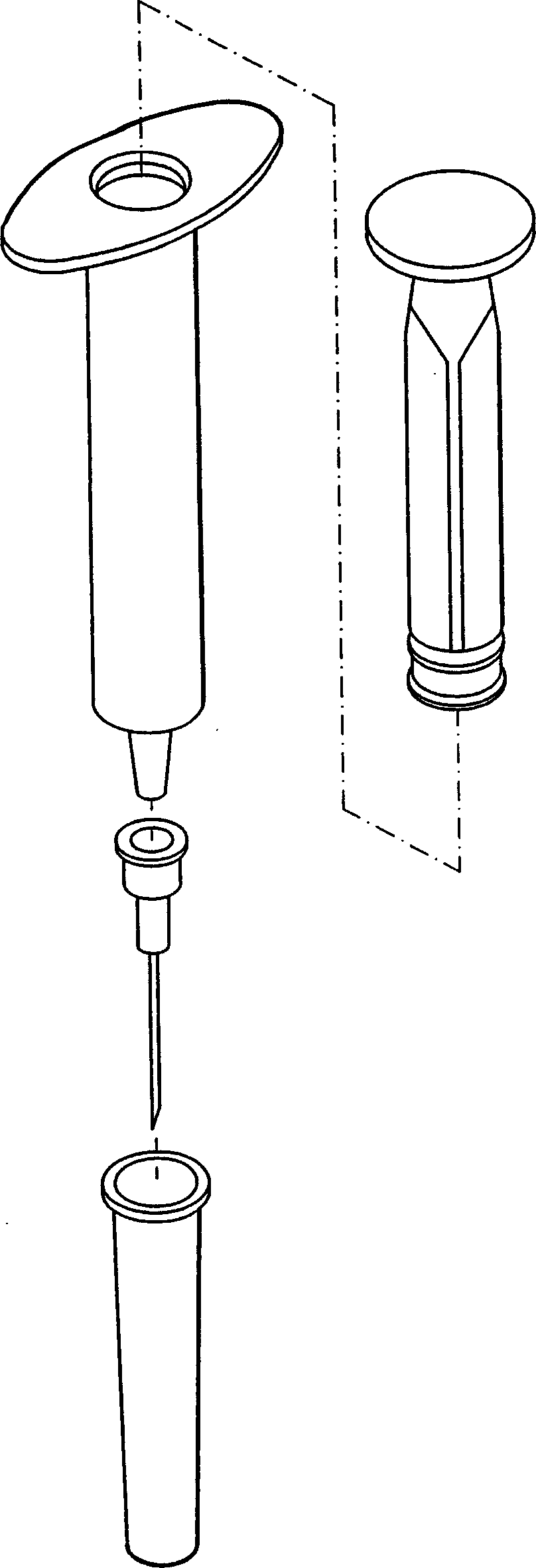
【Technical field】 [0001] The invention relates to a retractable safety injection syringe. 【Background technique】 [0002] see figure 1 , the traditional injection syringe is mainly composed of a hollow outer cylinder, a push rod and an injection needle, wherein the front end of the outer cylinder is integrally connected with a protrusion with a cone-shaped outer circumference and a hollow flow channel in the center Small tube, when installing the injection needle, hold the needle seat of the injection needle with your hand and insert it into the protruding small tube, and press the tapered cylindrical surface of the outer circumference of the protruding small tube to join with the needle seat of the injection needle; and the push rod is axially It is installed in the outer cylinder cavity, and the injection liquid is sucked into the cylinder cavity through the needle tube, the needle seat, and the protruding small tube through the pulling action of the push rod. When the i...

Claims


Application Information

Patent Timeline
Patent Type & Authority Applications(China)
IPC IPC(8): A61M5/178A61M5/32
Inventor 罗锦荣
Owner INTAI TECH CORP
Learn More