Image measuring head and image measuring system used for numerical control milling machine

A CNC milling machine and image measurement technology, which is applied in the direction of measurement/indicating equipment, metal processing machinery parts, metal processing, etc., can solve the problems of single point measurement and low measurement efficiency, so as to improve production efficiency, improve accuracy consistency, and replace The effect of convenient installation

Inactive Publication Date: 2016-03-30
TZTEK TECH
View PDF7 Cites 3 Cited by
  • Summary
  • Abstract
  • Description
  • Claims
  • Application Information

AI Technical Summary

Problems solved by technology

At the same time, because the three-coordinate probe adopts the contact measurement method, there are also the following shortcomings: single-point measurement, low measurement efficiency

Method used


Image

  • Image measuring head and image measuring system used for numerical control milling machine
  • Image measuring head and image measuring system used for numerical control milling machine

Examples


Embodiment 1

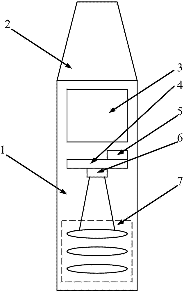
[0023] Such as figure 1 As shown, an image probe 14 for in-situ measurement of a CNC milling machine according to the present invention includes: a housing 1, a coupler 2, a camera module, a communication module 5, and a power supply module 3, wherein the coupler 2 Located at the end of the image measuring head 14, it is fixedly connected with the housing 1, and is used for connection with the spindle tool clamping mechanism of the CNC milling machine; the camera module, the communication module 5, and the power module 3 are arranged in the housing 1; The camera module group includes a camera 6, a lens 7, a camera driver board 4 and an image signal processor (preferably the communication module 5 is arranged on the camera driver board 4), and the power supply module 3 is connected to the camera driver board 4. The group is connected with the communication module 5 to provide electric energy for it. There are many ways to implement the power supply module 3. The battery can be...

Embodiment 2

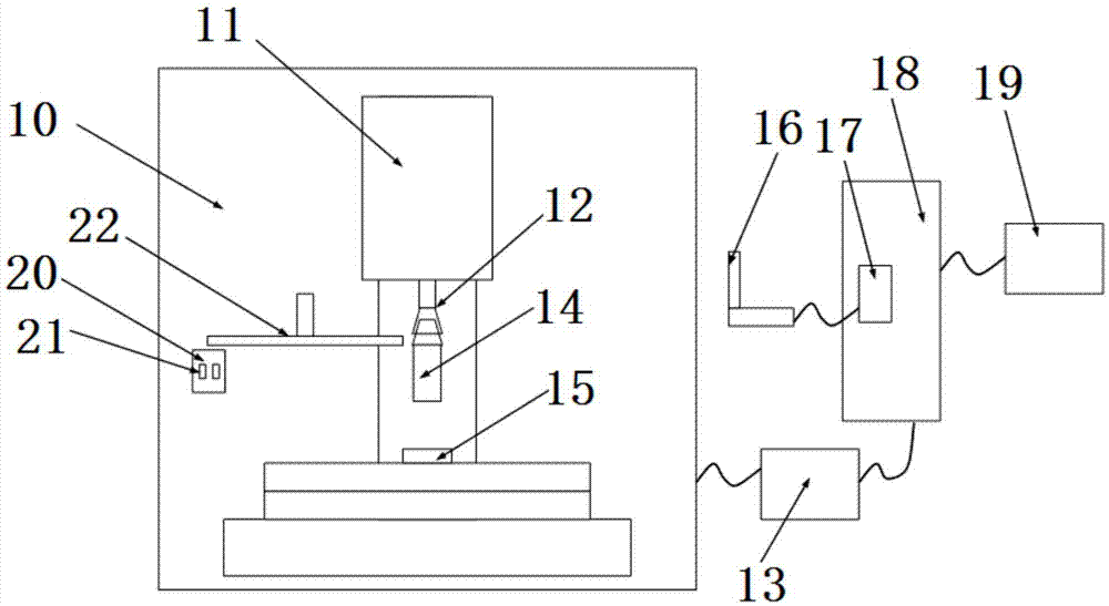
[0029] A video measurement system for in-situ measurement of CNC milling machines, such as figure 2 As shown, it includes a CNC machining center module 10, a control system 13, and a host computer, wherein the CNC machining center module 10 is connected to the control system 13, and performs corresponding detection under the control of the control system 13, and will detect The received image signal is sent to the host, and the host is used to process and display the image signal, wherein the numerical control machining center module 10 includes the image probe 14 described in Embodiment 1, and the image probe 14 is set above the workpiece 15 to be processed.

[0030] Preferably, the CNC machining center module 10 includes a spindle tool clamping mechanism 11, a video probe holder 20, and a video probe loading and unloading hand 22, wherein the video probe 14 is mounted on the spindle tool through a coupling 2. The clamping mechanism 11 is connected (here, the conical surfac...


PUM


Abstract

The invention discloses an image measuring head and an image measuring system used for a numerical control milling machine, and the image measuring head and the image measuring system are simple in structural design and are relatively low in cost. The image measuring head can be conveniently and quickly fixed to a main shaft like a tool used for the numerical control milling machine, so that on-position measuring is realized. Moreover, the tool and the measuring head are convenient and quick to replace. Meanwhile, the image measuring head and the image measuring system are high in measuring speed and are beneficial to improving the production efficiency. The measured data can be used as compensation basis of a next workpiece, so that precision consistency of different processed workpieces is improved. More importantly, the image measuring head and the image measuring system can be matched with each shaft of the numerical control milling machine to move, so that geometric quantity measuring for a plurality of processing surfaces of a complex processing part can be realized.

Description

technical field [0001] The invention relates to the measurement field of a numerically controlled milling machine, in particular to an image measuring head and an image measuring system for in-situ measurement of a numerically controlled milling machine. Background technique [0002] In the machining process, geometric measurement is an indispensable and important link. CNC milling machines (including machining centers) are widely used in mechanical processing, and three-coordinate measuring machines are important geometric measurement equipment. Both have similar mechanical structures, both use the Cartesian coordinate system, and both use high-precision position feedback components such as grating rulers. They are the same in action execution and opposite to each other in the direction of information conversion. Moreover, it is generally believed that the accuracy of the machining machine is an order of magnitude higher than that of the machined parts, and the accuracy of...

Claims


Application Information

Patent Timeline
Patent Type & Authority Applications(China)
IPC IPC(8): B23Q17/24B23Q17/20
CPCB23Q17/2471B23Q17/20B23Q2717/006
Inventor 王志伟
Owner TZTEK TECH
Why Eureka
Try Eureka