Optical disk device

An optical disc device and optical technology, which is applied to the configuration/installation of heads, recording/reproducing by optical methods, instruments, etc., can solve the problems of increasing operating hours, affecting the simplification of assembly, etc., so as to reduce operating hours and prevent falling off. Effect

Inactive Publication Date: 2006-05-03
PANASONIC CORP
View PDF1 Cites 1 Cited by
  • Summary
  • Abstract
  • Description
  • Claims
  • Application Information

AI Technical Summary

Problems solved by technology

[0003] However, if the connector is used as a fixing method, the man-hours will increase, and the tightening torque of the connector needs to be controlled, which affects the simplification of assembly.

Method used


Image

  • Optical disk device
  • Optical disk device
  • Optical disk device

Examples


Embodiment 1

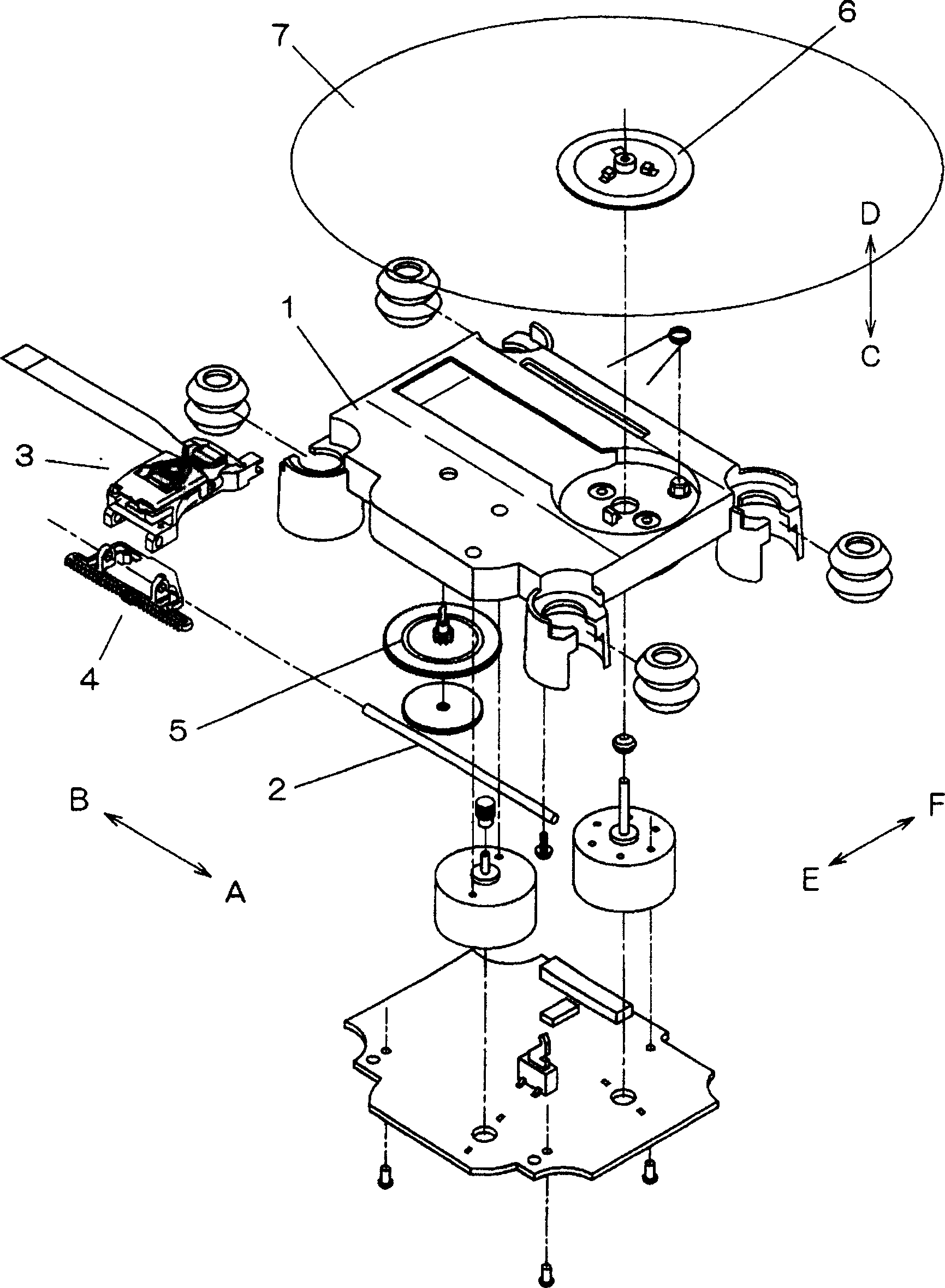
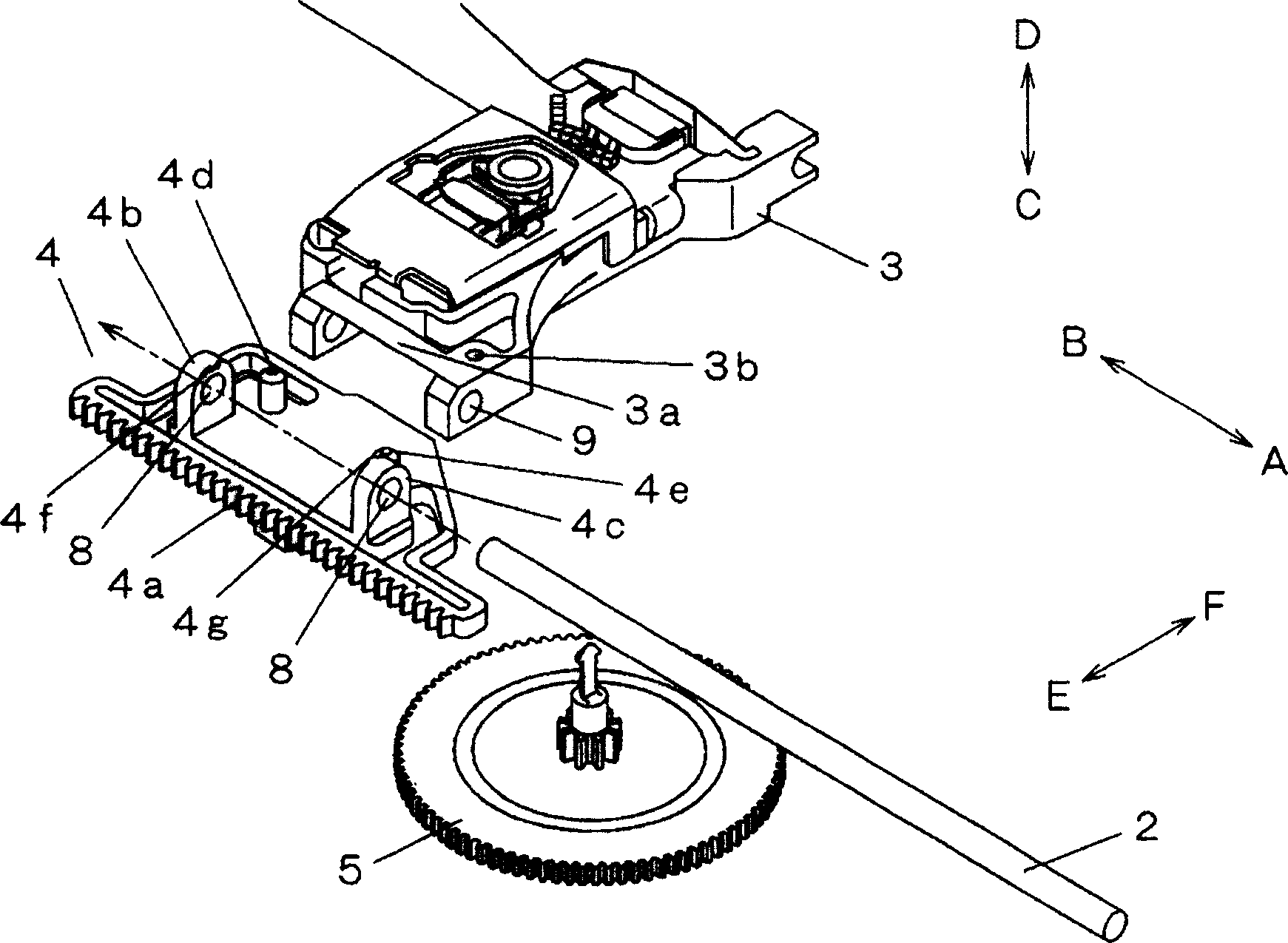
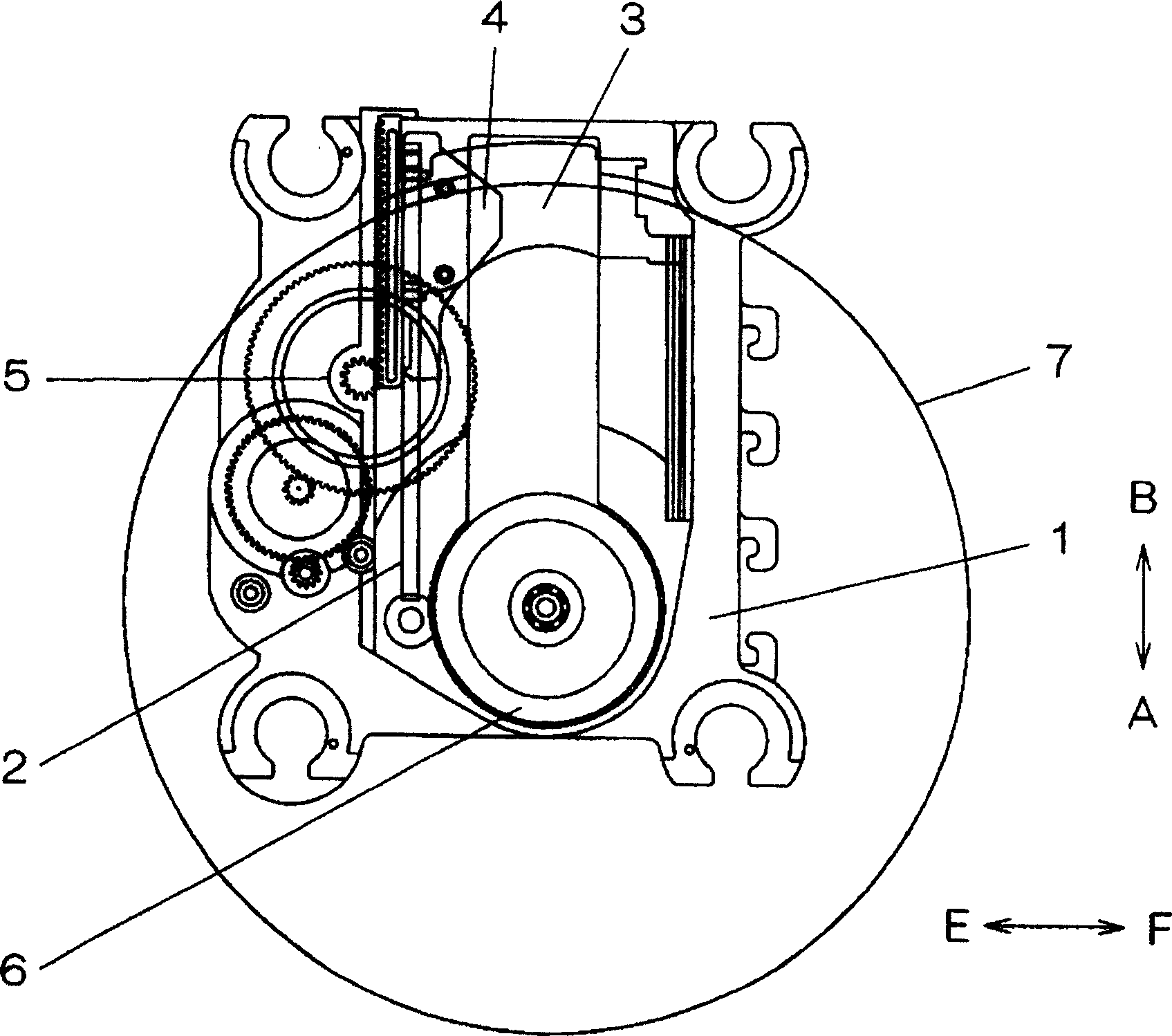
[0022] Embodiments of the present invention will be described below with reference to the drawings. figure 1 It is an exploded perspective view of the part structure in the device embodiment of the present invention, figure 2 yes figure 1 A zoomed-in perspective view of the vicinity of the optical pickup in the middle, image 3 is a plan view after the device is assembled in the present invention, Figure 4 is a plan view near the turntable in the above embodiment, Figure 5 From Figure 4 The side view indicated by the arrow Z direction in the middle, Figure 6 From Figure 4 The side view shown in the arrow Y direction in the middle, in order to better understand the above description, shows the section near the optical pickup 3 and the rack 4 ( Figure 4 X-X section).

[0023]In the figure, 7 is a recording medium for recording various signals, that is, a disk, 3 is an optical pickup for recording and reproducing signals on the disk 7, and is composed of a lens and ...


PUM


Abstract

The present invention relates to an optical disc device, which realizes cost reduction and simplification of assembly by fixing an optical pickup and a feed rack without a connecting member. Since the elastic holding part is arranged on the feed rack (4), the elastic holding part prevents looseness between the optical pickup (3) and the feed rack (4) , so as to maintain the positioning of the optical pickup in the A-B direction, and because the hook is provided on the holding part, it can also be used to maintain the positioning in the C-D direction, and the feed rack (4) Positioning pins are provided to maintain positioning in the EF direction, and the feed rack ( 4) Press against the optical pickup (3), thereby forming a structure in which the optical pickup (3) and the feed rack (4) can be fixed without connecting pieces.

Description

technical field [0001] The present invention relates to an optical disc device which has a simple structure by reducing the number of parts. Background technique [0002] The pickup driving mechanism for recording and reproducing on the optical disc is composed of a guide part, an optical pickup, a feed rack and a feed gear. The rack is firmly connected to the optical pickup and driven by the feed gear. For recording and reproduction of an optical disc, it is necessary to precisely control the feed amount of the optical pickup, and a structure to absorb the meshing gap between the feed gear and the feed rack is required. Usually, the rack portion of the feed rack is formed of resin, and the bending of the rack portion increases the meshing amount on the pitch line by virtue of the elasticity of the resin, thereby absorbing the meshing gap. And, in order to precisely control the feeding amount of the optical pickup, it is necessary to use a connecting member to fix the opti...

Claims


Application Information

Patent Timeline
Patent Type & Authority Applications(China)
IPC IPC(8): G11B7/085G11B7/09G11B21/02
Inventor 阿多口修胁川政直
Owner PANASONIC CORP
Why Eureka
Try Eureka