
USB connector plug

A connector plug, connector technology, applied in the direction of connection, fixed connection, two-part connection device, etc., can solve problems such as inconvenience in use, and achieve the effect of convenience in use

Inactive Publication Date: 2006-05-03
AIGO DIGITAL TECHNOLOGY CO LTD
View PDF1 Cites 23 Cited by
  • Summary
  • Abstract
  • Description
  • Claims
  • Application Information

AI Technical Summary

Problems solved by technology

[0005] In order to solve the disadvantage that the above-mentioned existing USB connector plug is only provided with connecting metal terminals on one side, which causes inconvenience to the user during use, the purpose of the present invention is to provide a standard USB socket that can be inserted into the front and back sides, and both sides can be inserted. A USB connector plug for signal transmission can be established, which is convenient to use

Method used


Image

  • USB connector plug
  • USB connector plug
  • USB connector plug

Examples


no. 1 example

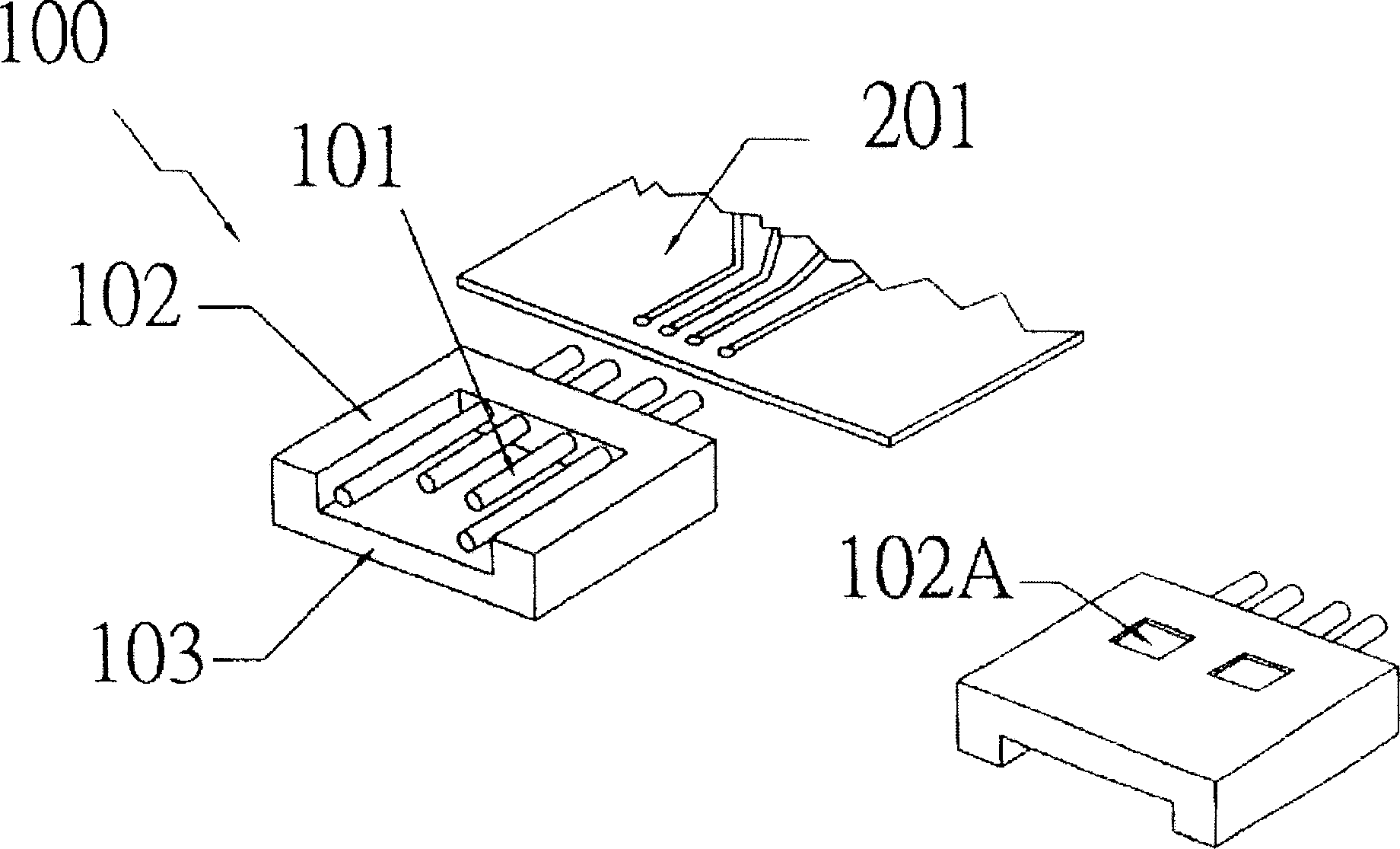
[0020] The USB connector plug of the present invention is matched with a standard USB interface socket, and includes a metal terminal in contact with an electrical contact on the tongue of the socket when inserted and a connector body carrying a metal terminal. The metal terminal includes two groups that can independently complete the standard The metal terminals for USB signal transmission are located on the opposite sides of the connector body. Such as image 3 , Figure 4 Shown is the first embodiment of the USB connector plug of the present invention, including a body 301 and a metal terminal 302. The body 301 includes an upper part and a lower part. The upper part includes an upper board seat 3011 and an upper carrier board 3012. The lower part includes The lower board seat 3013, the lower bearing board 3014, and the metal terminal 302 include two groups 3021 and 3022, which are respectively arranged on the upper part and the lower part of the body.

[0021] Please refe...


PUM


Abstract

The invention provides a USB connector plug which is matched with the standard USB interface plug. It comprises: a mental terminal which touches the conductivity contact of the plug tongue when plugging it and a connector body used to load the mental terminal, wherein the mental terminal is two groups of mental terminal which can independently finish the standard USB signal transmitting and are positioned on the opposite side of the connector body. It also arranges an isolating mechanism to avert the mental terminal to touch the plug external mental casing on the connector body.

Description

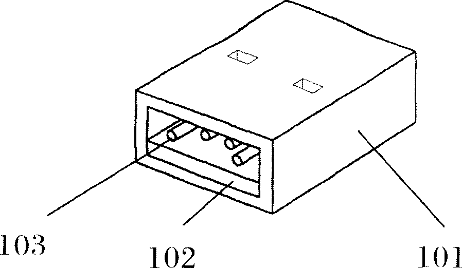
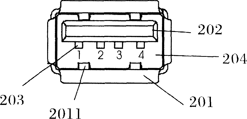
【Technical field】 [0001] The invention relates to a low-thickness connection device for a universal serial bus (USB) interface, in particular to a USB connector plug with double-sided connection, which belongs to the technical field of computer connectors. 【Background technique】 [0002] The existing Universal Serial Bus (hereinafter referred to as USB) interface connector has become a technical standard, Figure 1a plug for the USB device, figure 2 It is a standard USB socket located on peripheral devices such as computers. The plug includes a shell 101, a plug body 102, and a metal terminal 103 located on the plug body 102. The plug body 102 is close to the bottom wall in the shell 101 and carries the metal terminals. 103 faces upward, and there is a certain gap between it and the upper wall of the housing 101 . The socket includes a housing 201, a tongue 202, and an electrical terminal 203 arranged on the tongue 202. The tongue 202 is located in the housing 201, and the...

Claims


Application Information

Patent Timeline
Patent Type & Authority Applications(China)
IPC IPC(8): H01R12/55H01R24/00H01R43/16
CPCH01R24/60H01R2107/00
Inventor 周朝晖
Owner AIGO DIGITAL TECHNOLOGY CO LTD
Learn More