Medical needle device having shield with wings

A shield and shaft core technology, applied in the direction of needles, guide needles, instruments introduced into the body, etc., can solve the problem that the shield bending is not considered

Inactive Publication Date: 2006-05-03
JMS CO LTD
View PDF2 Cites 5 Cited by
  • Summary
  • Abstract
  • Description
  • Claims
  • Application Information

AI Technical Summary

Problems solved by technology

[0006] On the other hand, in the case of the above-mentioned conventional medical needle device with a winged shield having a needlestick injury prevention function, the possibility of the shield being partially bent is not considered.

Method used


Image

  • Medical needle device having shield with wings
  • Medical needle device having shield with wings
  • Medical needle device having shield with wings

Examples


Embodiment 1

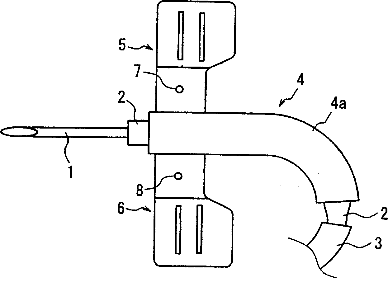
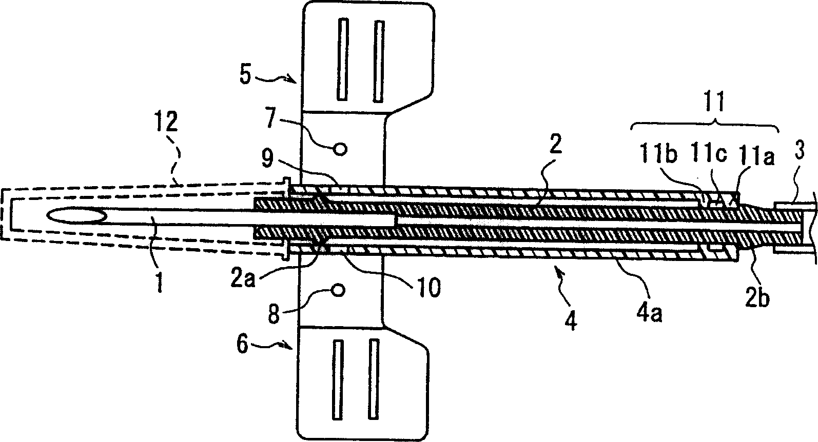
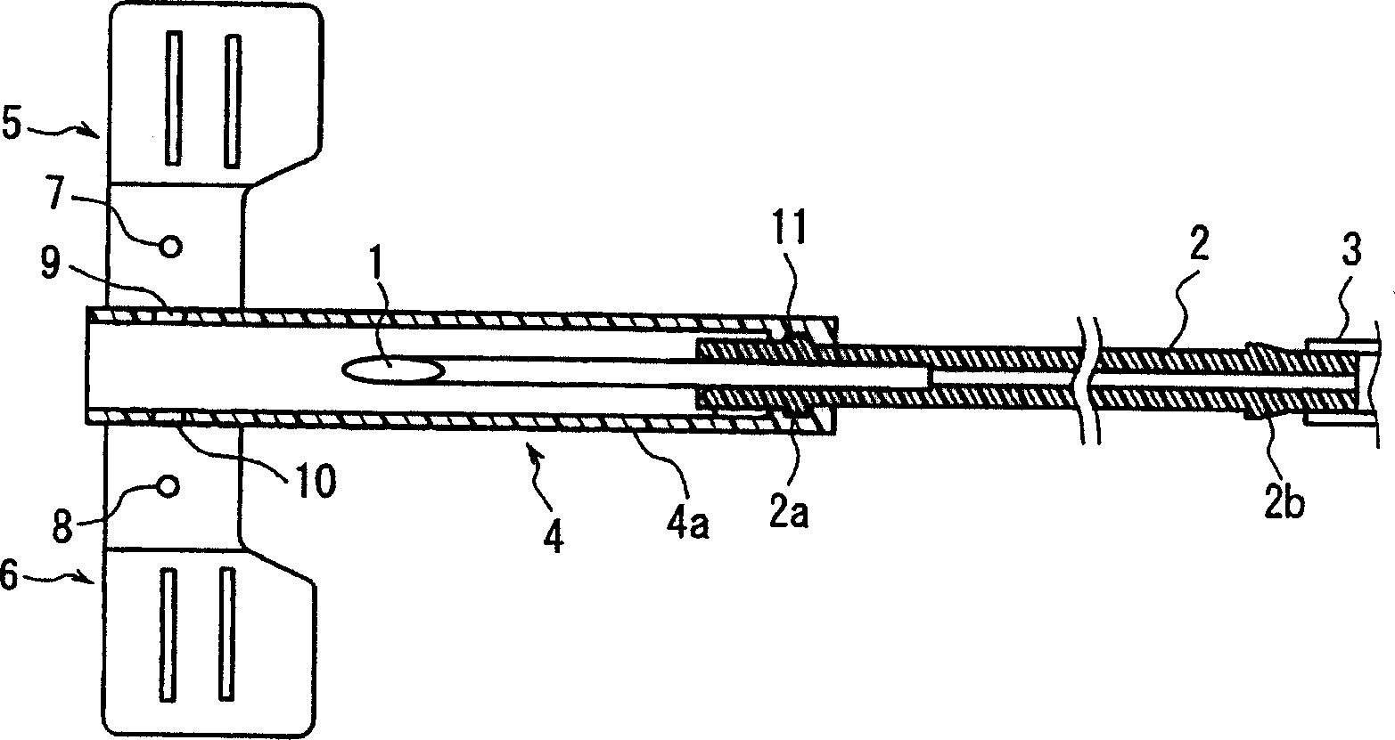
[0024] figure 1 is a top view of the medical needle device according to Embodiment 1 of the present invention. Reference numeral 1 denotes a needle fixed to the front end of a resin-made core 2 . A tube 3 is connected to the rear end of the shaft core 2 . Reference numeral 4 denotes a winged shroud including a substantially cylindrical shroud tube 4 a made of resin, and a left wing portion 5 and a right wing portion 6 . The axially movable needle 1 and the mandrel 2 are inserted into the inner hole of the shield tube 4a. The left wing 5 and the right wing 6 are provided at the front end portion of the shield tube 4a, ie at the end from which the needle 1 protrudes. Here, the wings are not necessarily located at the front end edge of the shield tube 4a, and may be located closer to the front end of the shield tube 4a than the center of the shield tube 4a if appropriate. The wings 5 ​​and 6 are respectively connected to both sides of the outer surface of the shield tube 4a,...

Embodiment 2

[0032] A medical needle device with a winged shield according to embodiment 2 such as Figure 4 shown. The needle 21 is held in the bore of a cylindrical mandrel 22 . The shaft core 22 includes a small-diameter portion 22a on the needle 21 side and a large-diameter portion 22b on the rear side of the small-diameter portion 22a. The needle 21 is clamp-mounted to the small-diameter portion 22a. One of the ends of the connecting thin tube 23 is fitted to the large-diameter portion 22b. The other end portion of the connecting thin tube 23 is fitted to the large-diameter portion 24 a of the cylindrical adapter 24 . Therefore, the medical needle device has a structure in which the shaft core 22 and the adapter 24 are connected by the connecting thin tube 23 . The tube 25 is fitted to the small-diameter portion 24b of the adapter 24 . As described above, a continuous hole is formed from the tube 25 to the needle 21 . The shaft core 22 is made of a flexible resin material.


PUM


Abstract

A medical needle device having a winged shield (4) with a pair of wings (5, 6) located at the front end side of a generally annular tubular shield tube (4a) . The shaft core (2) is axially movably inserted into the inner hole of the shield tube, and the needle tube (1) is installed at the front end of the shaft core. An infusion tube (3) can be connected to the rear end of the hub, and the front end of the needle tube can be received in the inner hole of the shield tube. The shield tube together with the needle cannula can be bent at least partially in the axial direction when the needle protrudes from the front end of the needle cannula and engages the needle cannula. This allows the shield tube, even with wings, to be bent into curves, and the bending can be done in close proximity to the needle.

Description

technical field [0001] The present invention relates to medical needle devices, and more particularly, the present invention relates to a medical needle device having a winged shield for needle stick injury prevention, in which the needle can be safely stored after use. Background technique [0002] Winged medical needle devices are widely used in treatments such as infusion, blood transfusion, and extracorporeal blood circulation. As an example of it, such as Figure 8A with 8B Winged indwelling needles as shown are well known. This winged indwelling needle has a configuration in which a needle 31 is held at the front end of a hub 33 having wings 32 and an infusion tube 34 can be connected to the rear end of the hub 33 . Reference numeral 35 denotes a needle cap mounted on the needle 31 . During infusion, the wings 32 are secured to the patient's arm or the like by adhesive tape or similar means, thereby maintaining the insertion of the needle 31 . [0003] Meanwhile, c...

Claims


Application Information

Patent Timeline
Patent Type & Authority Applications(China)
IPC IPC(8): A61M5/158A61M5/32A61M25/06
CPCA61M5/158A61M5/3243A61M25/0612A61M25/0631A61M25/0637
Inventor 森胁邦治本乡奖清野隆史
Owner JMS CO LTD
Why Eureka
Try Eureka