Method for bending wave spring with concave hole

A wave spring and concave hole technology, applied in the field of stamping, can solve the problems of increased scrap rate and breakage, and achieve the effects of improving productivity, reducing scrap rate and good coincidence.
CN102896185BInactive Publication Date: 2014-11-05LUOYANG BEARING RES INST CO LTD

Patent Information

Authority / Receiving Office
CN Β· China
Patent Type
Patents(China)
Current Assignee / Owner
LUOYANG BEARING RES INST CO LTD
Publication Date
2014-11-05
Estimated Expiration
Not applicable Β· inactive patent

Smart Images

  • Figure 1
    Figure 1
  • Figure 2
    Figure 2
  • Figure 3
    Figure 3
Patent Text Reader

Abstract

The invention discloses a method for bending a wave spring with concave holes. The wave spring (7) to be bent has a width B and a thickness K and is provided with a plurality of concave holes; a pad plate (1) and a concave die (2) are fixed on a working table of a press machine through threaded through holes (8) of the concave die; a positioning pin (6) is installed inside a positioning pin hole (9); a convex die (3) is linked with a punching platform of the press machine through a threaded through holes (3.1) of the convex die; as N equals to M, a bending pressure head (5) can enter a bending groove (10); when the wave spring to be bent is positioned through the positioning pin, the punching platform moves downwards to bend the wave spring to be bent from the concave holes, and the bent parts of the wave spring meet the requirements of H and r; and the bent wave spring to be bent is taken out from the bending groove and moved to a discharge groove (11) so as to accomplish the bending process of the wave spring to be bent at one of the concave holes. The wave spring can be formed by repeating the bending process, the productivity is improved, and the rejection rate is reduced.
Need to check novelty before this filing date? Find Prior Art

Description

technical field

[0001] The invention belongs to the technical field of stamping, and in particular relates to a bending method of a wave spring with a concave hole.
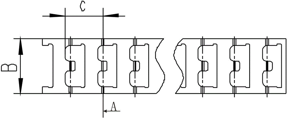
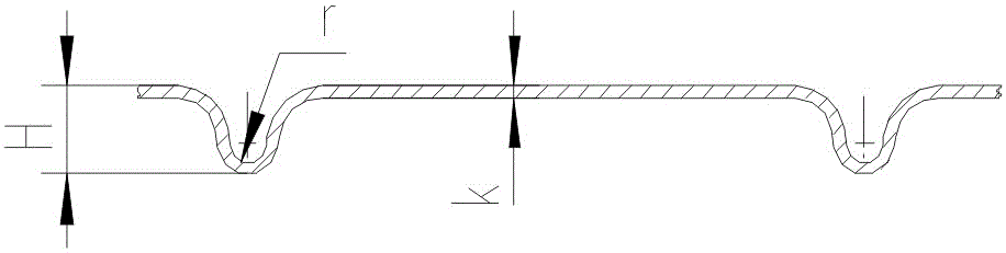
 Background technique

[0002] figure 1 It is a schematic diagram of the expansion of the wave spring to be bent when it is not bent. On the wave spring, there are several concave holes that have been stamped and are approximately concave. The line connecting the two convex parts of one concave hole to the other adjacent The distance between the symmetrical centerlines of the two convex parts of the concave hole is set to C, figure 1 The A line marked in is the symmetrical center line of the two convex parts of the concave hole, figure 1 The subscript B is the width of the wave spring.

[0003] figure 2 is a schematic cross-sectional view of the wave spring during bending. The wave spring starts to bend from the line A of each concave hole. The inner radius of each bend is set to r, and the two outer radii of...

Claims
