Mechanical arm fixed block for light blockage coating machine

A technology of robotic arms and fixed blocks, which is applied to robotic arms, devices for coating liquid on the surface, coatings, etc., can solve problems such as pipeline breakage, breakage, and impact on chip quality, and reduce the risk of pipeline damage Possibility, reducing the difference in hardness, reducing the effect of short life

Inactive Publication Date: 2009-05-20
HEJIAN TECH SUZHOU
View PDF0 Cites 0 Cited by
  • Summary
  • Abstract
  • Description
  • Claims
  • Application Information

AI Technical Summary

Problems solved by technology

[0004] 1. The inner wall of the existing fixed block is usually cylindrical. If the position of the pipeline is not appropriate or the length is not suitable during the fixing process, it will increase the force on the pipeline during the movement of the mechanical arm and increase its damage. possibility;
[0005] 2. The pipeline material used in the machine is usually Teflon tube, and the hardness of the fixing block used for positioning is usually higher than the surface hardness of the Teflon tube, so the pipeline may be broken during the movement of the robot arm very big
[0006] 3. The outer covering wire of the sensor signal wire on the robot arm is not tough enough, and it is easy to break during long-term movement
[0007] Due to the existence of the above defects, as the robotic arms 1 and 2 move during the photoresist coating and development process, the pipeline fixed on the robotic arm will also move back and forth accordingly, and dust will be generated due to the breakage of the pipeline after a long time , causing pollution to the environment of the machine, affecting the normal operation of the robotic arm, and also affecting the quality of the chip

Method used


Image

  • Mechanical arm fixed block for light blockage coating machine
  • Mechanical arm fixed block for light blockage coating machine
  • Mechanical arm fixed block for light blockage coating machine

Examples


Embodiment Construction

[0019] The present invention will be further described below in conjunction with the accompanying drawings.

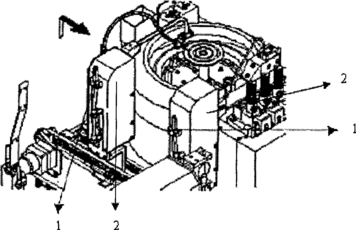
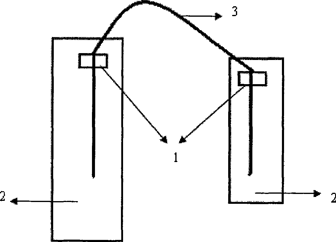
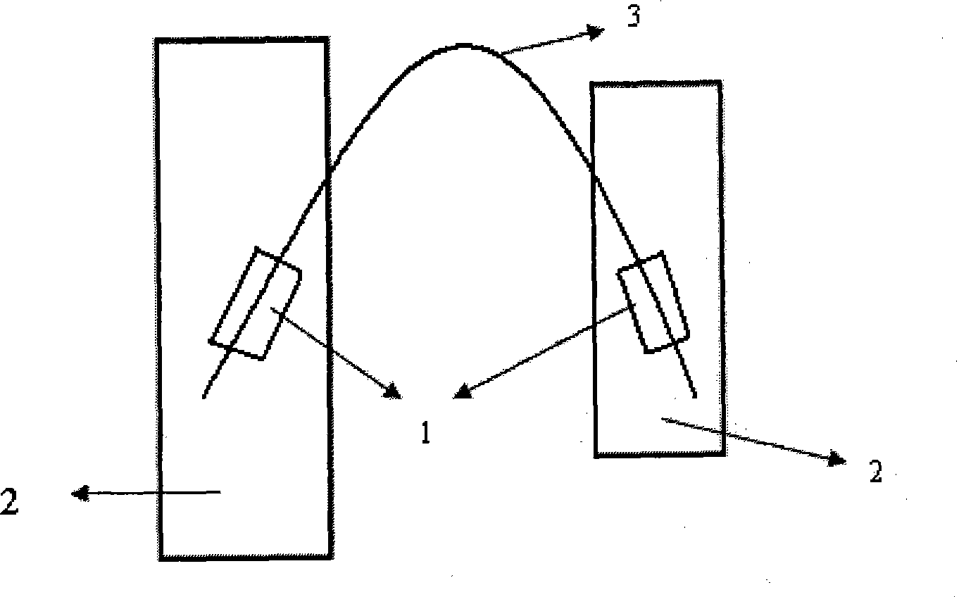
[0020] Such as image 3 As shown, a mechanical arm fixed block 1 for a photoresist coating machine is arranged in the middle of the mechanical arm 2. The outer contour of the fixed block 1 is rectangular in front view, and can also be in any other suitable shape. Here No limitation; the fixed block 1 is arranged at a certain oblique angle relative to the mechanical arm 2, and its longitudinal axis intersects the longitudinal axis of the mechanical arm 2 at an acute angle, so that the fixed block 3 of the pipeline 3 on the two mechanical arms Between the natural bending, not easy to break.

[0021] combine Figure 4 and Figure 5 , the longitudinal and transverse cross-sectional views of a mechanical arm fixing block 1 for a photoresist coating machine of the present invention. The inner wall of the fixed block of the mechanical arm in the present invention is in th...


PUM


Abstract

The invention relates to a mechanical arm fixing block for a photoresist coating machine. The inner wall of the fixing block is a truncated cone shaped through hole and is used for receiving a pipeline; the fixing block is arranged at the middle part of a mechanical arm, and the longitudinal axis of the fixing block is intersected with that of the mechanical arm at an oblique angle. The adoption of a structure and a fixing mode of the mechanical arm fixing block can overcome dust caused by the loss of the pipeline in the prior art.

Description

technical field [0001] The invention relates to a fixing device, in particular to a fixing block of a mechanical arm used for a photoresist coating machine. Background technique [0002] On the mechanical arm of the photoresist coating machine, there is usually a mechanical arm fixing block, which is used to fix the control gas pipeline and sensor signal line in the coating and developing process, so as to make it work better. [0003] Such as figure 1 As shown, the existing mechanical arm fixing block is usually arranged on the upper part of the mechanical arms 1 and 2 of the photoresist coating machine, and is used to fix the control gas pipeline and sensor signal line in the coating and developing process. figure 2 The setting position of the fixing block of the robot arm and the fixing method of the pipeline group are more clearly shown in . Under the action of the mechanical arm fixing block 1, the pipeline group is firmly fixed on the mechanical arm and cannot move ...

Claims


Application Information

Patent Timeline
Patent Type & Authority Applications(China)
IPC IPC(8): B25J19/00B05C21/00F16L3/01
Inventor 胡珂
Owner HEJIAN TECH SUZHOU
Why Eureka
Try Eureka