Metal sheet bending equipment

A sheet metal and equipment technology, applied in the field of sheet metal processing equipment, can solve problems such as injury to personnel body parts, high pressure of hydraulic system, and reduced effect, and achieve the effects of preventing personnel injury, prolonging equipment life, and simple equipment structure.

Inactive Publication Date: 2020-06-12
王宏斌
View PDF0 Cites 0 Cited by
  • Summary
  • Abstract
  • Description
  • Claims
  • Application Information

AI Technical Summary

Problems solved by technology

[0002] There are many problems in the bending and stamping of sheet metal. Because the upper and lower molds need to be overlapped during the stamping process, and the steel plate and other materials are bent and stamped, there are many problems in the process. First, due to the stamping The contact between the mold and the material during the cutting process will cause the passivation of the mold, and in many cases, the effect of bending and stamping will be reduced, and because the upper mold needs to be driven upward by th

Method used


Image

  • Metal sheet bending equipment
  • Metal sheet bending equipment
  • Metal sheet bending equipment

Examples


Embodiment Construction

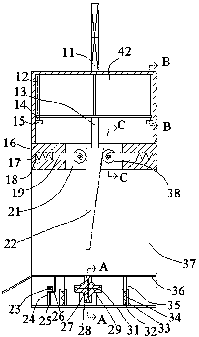
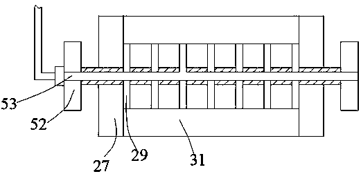
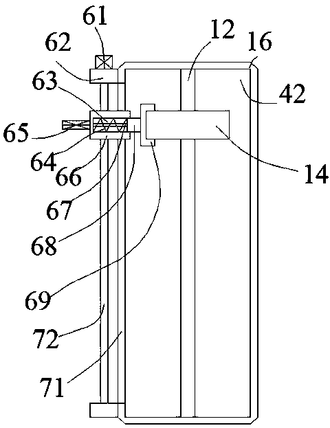
[0020] Such as Figure 1-Figure 4 As shown, the present invention is described in detail. For the convenience of description, the orientations mentioned below are now stipulated as follows: figure 1 The up, down, left, right, front and back directions of the projection relationship itself are consistent. A sheet metal bending equipment of the present invention includes a box body 16, and the box body 16 is provided with a penetrating inner cavity 37, and the upper end of the inner cavity 37 is A penetrating inner cavity 21 is communicated in the wall, and a top inner cavity 42 is communicated in the upper end wall of the penetrating inner cavity 21. A top hydraulic cylinder 11 is fixed on the upper end of the box body 16, and the top hydraulic cylinder 11 The lower power connection is provided with a bottom fixing rod 13 located in the top inner cavity 42, the lower end surface of the bottom fixing rod 13 is fixed with an upper mold 22, and the top inner cavity 42 is fixed wit...


PUM


Abstract

The invention discloses metal sheet bending equipment. The equipment comprises a box, a passing inner cavity is formed in the box in a penetrating mode, a penetrating inner cavity is formed in the upper end wall of the passing inner cavity in a communicating mode, a top inner cavity is formed in the upper end wall of the penetrating inner cavity in a communicating mode, a top hydraulic cylinder isfixedly arranged on the upper end face of the box, a bottom fixing rod located in the top inner cavity is arranged on the lower side of the top hydraulic cylinder in a power connection mode, an upperdie is fixedly arranged on the lower end face of the bottom fixing rod, side bosses are fixedly arranged in the end walls of the two sides of the top inner cavity in a symmetrical mode, a vertical rod is fixedly arranged between each side boss and the upper end wall of the top inner cavity, lifting mating plates are arranged on the outer surfaces of the vertical rods in a sliding mode, and the lifting mating plates are fixed with the bottom fixing rod. According to the equipment, the structure is simple, and the upper die and a lower die are subjected to oil lubrication, so that bending is efficient, and the service life of the equipment is prolonged; and meanwhile, a structure for preventing personnel from being injured is arranged so that the personnel can safely use the equipment.

Description

technical field [0001] The invention relates to the technical field of sheet metal processing equipment, in particular to sheet metal bending equipment. Background technique [0002] There are many problems in the bending and stamping of sheet metal. Because the upper and lower molds need to be overlapped during the stamping process, and the steel plate and other materials are bent and stamped, there are many problems in the process. First, due to the stamping The contact between the mold and the material during the cutting process will cause the passivation of the mold, and in many cases, the effect of bending and stamping will be reduced, and because the upper mold needs to be driven upward by the hydraulic system after it moves downward , due to the heavy mold, the pressure of the hydraulic system is relatively high during the upward movement of the mold, which makes the hydraulic system easy to damage, and due to the aging of some electrical components or the aging of th...

Claims


Application Information

Patent Timeline
IPC IPC(8): B21D5/02B21D37/18
CPCB21D5/02B21D37/18
Inventor 王宏斌
Owner 王宏斌
Why Eureka
Try Eureka