Hermetic compressor

A compressor, closed technology, applied in the direction of liquid variable capacity machinery, mechanical equipment, variable capacity pump components, etc., can solve the problems of reducing compressor efficiency, increasing compressor input power, etc., reducing sliding surface, improving Efficiency, the effect of maintaining stability

Inactive Publication Date: 2006-05-10
TAIZHOU LG ELECTRONICS REFRIGERATOR CO LTD
View PDF0 Cites 5 Cited by
  • Summary
  • Abstract
  • Description
  • Claims
  • Application Information

AI Technical Summary

Problems solved by technology

[0009] However, in the hermetic compressor of the prior art as described above, there is a problem that the above-mentioned piston 7 rapidly performs linear reciprocating motion inside the compression chamber 6'.
Therefore, the entire inner wall of the compression chamber 6' and the outer circumference of the piston 7 rub against each other, and this friction increases the input power of the compressor, causing the problem of a decrease in the efficiency of the compressor.

Method used


Image

  • Hermetic compressor
  • Hermetic compressor
  • Hermetic compressor

Examples


Embodiment Construction

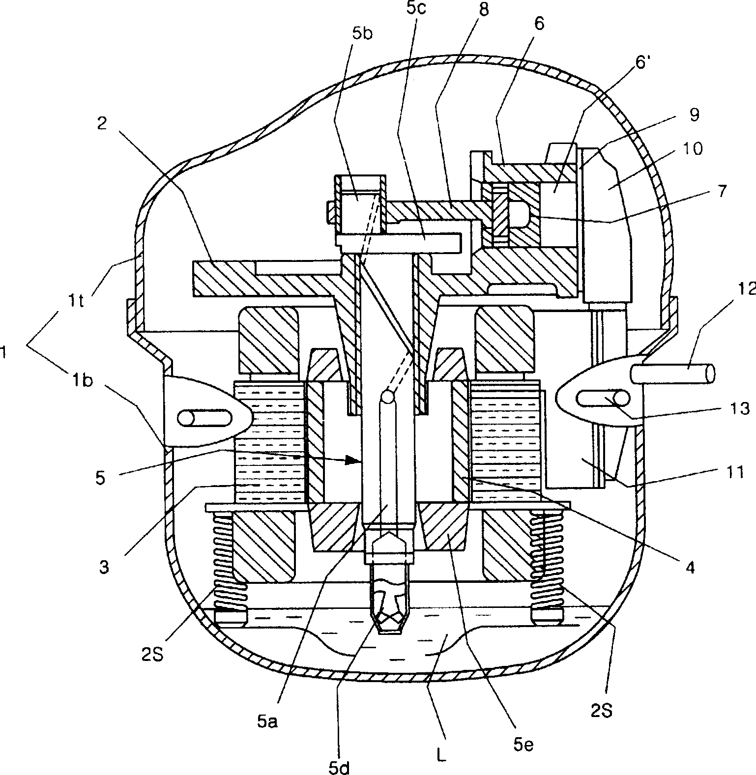
[0041] Embodiments of the hermetic compressor of the present invention will be described in detail below with reference to the accompanying drawings.

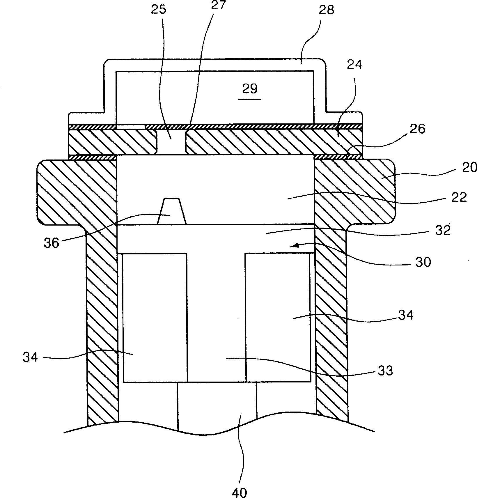
[0042] image 3 shows a cross-sectional view of the middle portion of an embodiment of the hermetic compressor of the present invention; Figure 4 shows the oblique view of the piston structure that constitutes the embodiment of the present invention; Figure 5 A cross-sectional view reflecting the structure of a piston constituting an embodiment of the present invention; Figure 6 A cross-sectional view showing the relationship between the volume space and the discharge hole of an embodiment of the present invention is shown in .

[0043] According to above-mentioned each figure, the frame that airtight container interior is provided with cylinder 20 is housed. A compression chamber 22 is formed through the front and back of the cylinder 20 . In order to block one side of the compression chamber 22, a valve groove 24 is pr...


PUM


Abstract

The invention discloses a closed-style compressor, which comprises the following parts: specific shaped piston 30, cylinder 20, compression chamber 22, guiding face 33, drainage hole 25 and bulk space 36, wherein the guiding face 33 is formed around the outer column face of piston and composed of piston length direction symmetrically, which slides in the cylinder 20 and compression chamber 22 within the more than 40 deg arc scale of piston length direction central axle; the bulk space 36 engages the drainage hole 25 of working fluid from compression chamber 22 in front of piston projection part, whose front displays flush conical shape deflecting from the length direction center of piston 30. The invention can improve the compressor working efficiency.

Description

technical field [0001] The present invention relates to a hermetic compressor, and more specifically relates to the invention of a hermetic compressor that compresses a working fluid during the linear reciprocating motion of a piston inside a compression chamber of a cylinder. Background technique [0002] exist figure 1 The structure of a prior art hermetic compressor is illustrated in a cross-sectional view. [0003] First, the airtight container 1 is composed of an upper container 1t and a lower container 1b, and forms an airtight space inside. A frame 2 is arranged inside the airtight container 1 . A stator 3 is fixed on the bottom of the frame 2, and the stator 3 is supported inside the airtight container 1 by a spring 2S. The rotor 4 is designed to pass through the center of the stator 3 and rotate with the stator 3 according to electromagnetic action. The rotor 4 is integrally connected with the crankshaft 5 penetrating through the central part of the frame 2 to r...

Claims


Application Information

Patent Timeline
Patent Type & Authority Applications(China)
IPC IPC(8): F04B27/08F04B39/12F04B53/14
Inventor 朴东佑郑珉圭
Owner TAIZHOU LG ELECTRONICS REFRIGERATOR CO LTD
Why Eureka
Try Eureka