Pattern forming method and pattern forming apparatus

A pattern and linear technology, applied in the field of forming patterns on the substrate, can solve the problems such as difficult to form lattice patterns

Inactive Publication Date: 2006-05-17
DAINIPPON SCREEN MTG CO LTD
View PDF2 Cites 7 Cited by
  • Summary
  • Abstract
  • Description
  • Claims
  • Application Information

AI Technical Summary

Problems solved by technology

In the method of Document 1, stripe patterns can be easily formed, but lattice patterns are difficult to form

Method used


Image

  • Pattern forming method and pattern forming apparatus
  • Pattern forming method and pattern forming apparatus
  • Pattern forming method and pattern forming apparatus

Examples


Embodiment Construction

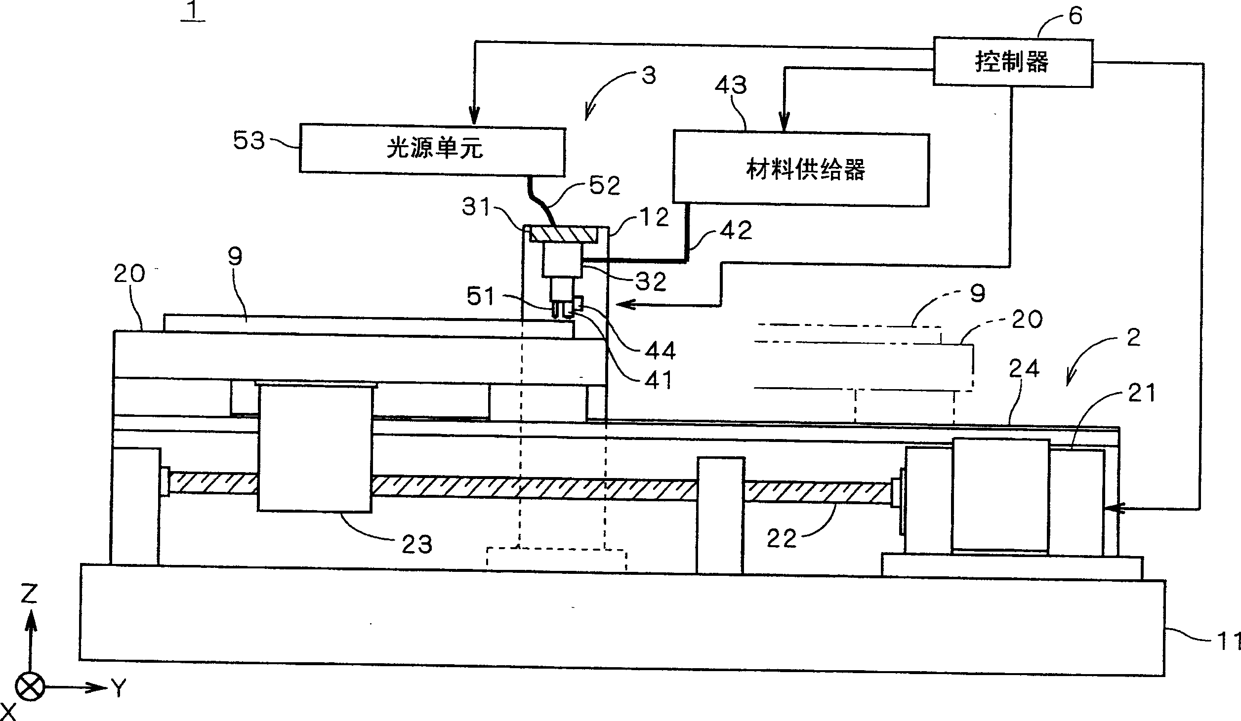
[0027] figure 1 is a configuration view of a patterning device according to a first preferred embodiment of the present invention. The pattern forming device 1 is a device for forming a pattern corresponding to a plurality of isolation ribs on a plasma display glass substrate (hereinafter referred to as "substrate") 9, and the substrate 9 on which the pattern is formed is formed by other methods. Becomes the panel (usually the rear panel) that is a component of a plasma display.

[0028] The pattern forming device 1 includes a stage moving mechanism 2 provided on a base 11 . Then, the workbench 20 for fixing the substrate 9 can be moved along the main surface of the substrate 9 (i.e. figure 1 shown in the Y direction) to move. In addition, the frame 12 is fixed on the base 11 to traverse the working platform 20 . Furthermore, the head 3 is connected to the frame 12 .

[0029] The table moving mechanism 2 includes a motor 21 connected with a ball screw 22 , and also includ...


PUM


Abstract

The invention provides a pattern forming method and a pattern forming device. The pattern forming device (1) includes a spraying member (41) for spraying a pattern forming material from a plurality of spray ports onto a main surface of a substrate (9). Through the table moving mechanism (2), the ejection member (41) moves relative to the substrate (9) in one direction along the main surface of the substrate (9), thereby forming a plurality of linear pattern elements on the substrate (9). In the process of forming the linear pattern element, the moving speed of a plurality of injection ports relative to the substrate (9) is periodically changed by the injection port moving mechanism (44), and a node is formed in each linear pattern element (91) , each node expands in a direction perpendicular to the direction in which the linear pattern element (91) extends. This makes it possible to properly form a pattern like a lattice-like structure on the substrate (9) while ejecting the pattern forming material from a plurality of ejection ports.

Description

technical field [0001] The present invention relates to a technique for forming a pattern on a substrate. Background technique [0002] Sandblasting (also known as "photolithography"), screen printing, lift-off process, and other similar methods have traditionally been considered as methods for forming barrier ribs in plasma display panels ( rib) pattern (setting of isolation ribs). However, the techniques cited above are complicated and thus increase the manufacturing cost. [0003] Under the circumstances described above, a technique such as that disclosed in Japanese Patent Application Laid-Open No. Hei 2002-184303 (Document 1) has been developed in recent years. According to the new technology, a paste-like patterning material containing a photocurable resin is sprayed onto a substrate from a nozzle having a plurality of small injection ports to form a stripe-shaped barrier rib pattern on the substrate; subsequently, the patterning material is subjected to UV treatmen...

Claims


Application Information

Patent Timeline
Patent Type & Authority Applications(China)
IPC IPC(8): H01J9/02B05C5/00B05D1/26G03F7/20H01J11/02H01J17/04H01L21/027
CPCB05C5/0216B05C9/14H01J9/241H01J9/02H01J11/20H01L21/20
Inventor 矢部学
Owner DAINIPPON SCREEN MTG CO LTD
Why Eureka
Try Eureka