Orthogonal ring antenna

A loop antenna and antenna technology, applied in loop antennas, antennas, electrical components, etc., can solve problems such as insufficient bandwidth, and achieve the effects of wide bandwidth, large gain, and good wind resistance

Inactive Publication Date: 2006-05-17
LANZHOU UNIVERSITY
View PDF1 Cites 3 Cited by
  • Summary
  • Abstract
  • Description
  • Claims
  • Application Information

AI Technical Summary

Problems solved by technology

However, when this antenna is used for TV transmission, there is still a problem of insufficient bandwidth, and one antenna can only transmit programs of one channel

Method used


Image

  • Orthogonal ring antenna
  • Orthogonal ring antenna
  • Orthogonal ring antenna

Examples


Embodiment Construction

[0017] Below in conjunction with accompanying drawing and embodiment the present invention is explained in detail:

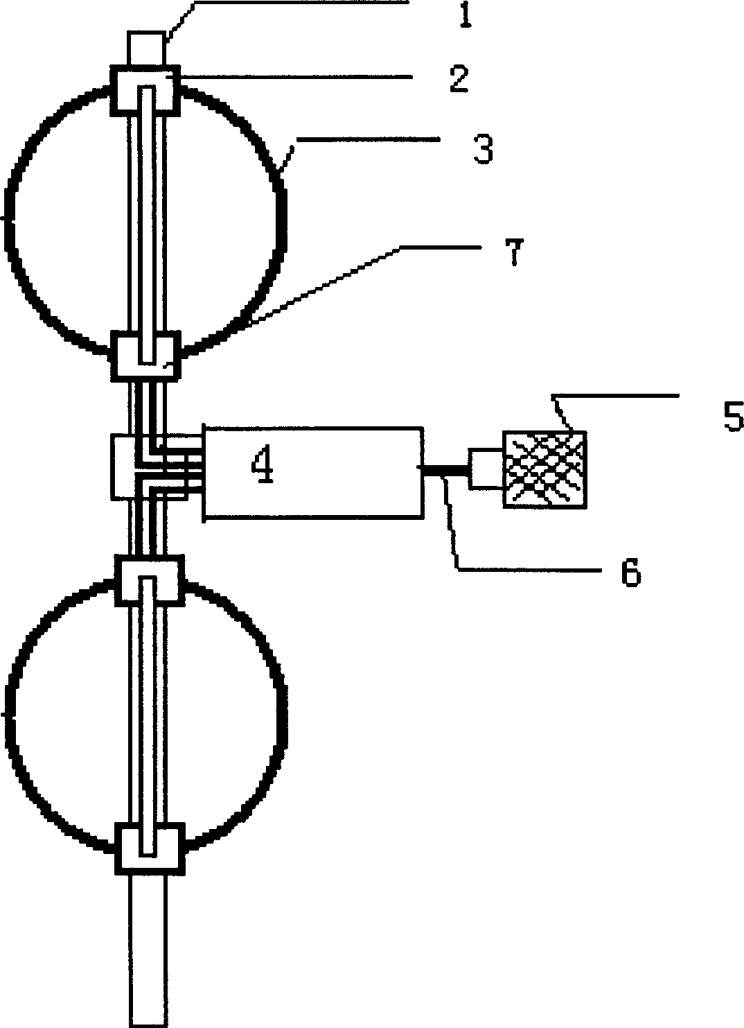
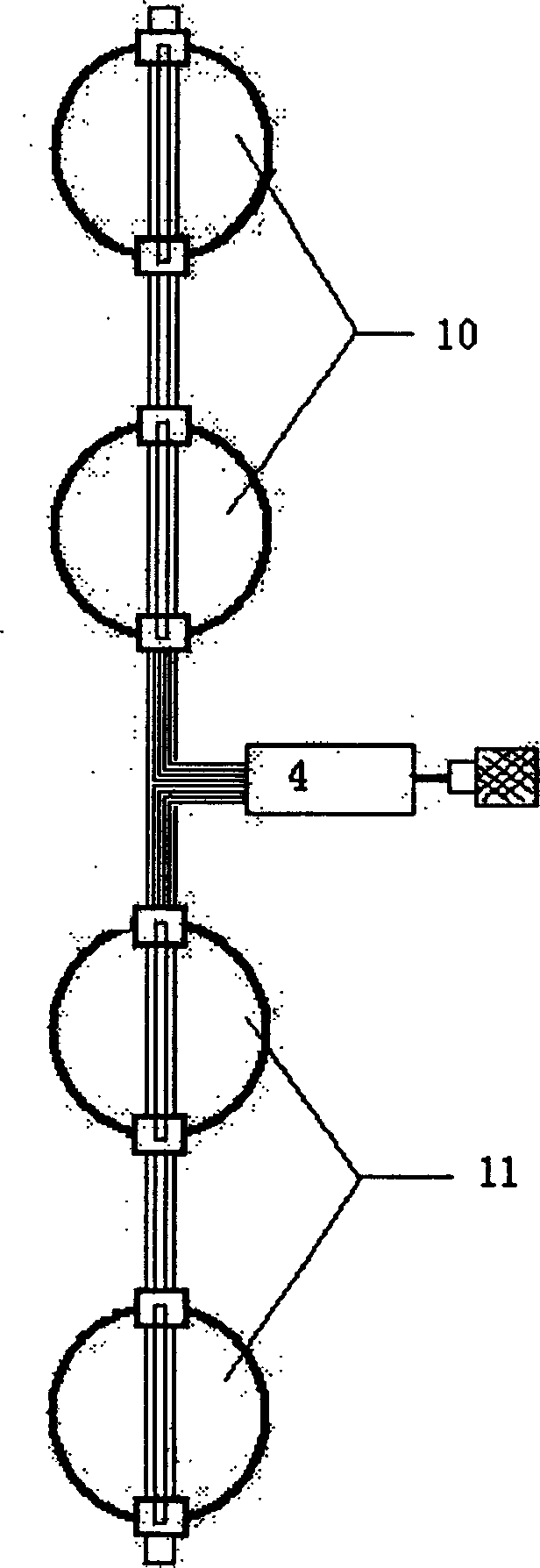
[0018] attached figure 1 The structure of a unit antenna of the present invention and the attached image 3 Given the structure of the two-element antenna with n=1, the structure of the orthogonal loop, the structure of each loop, and the setting of the feeder in the loop are the same.

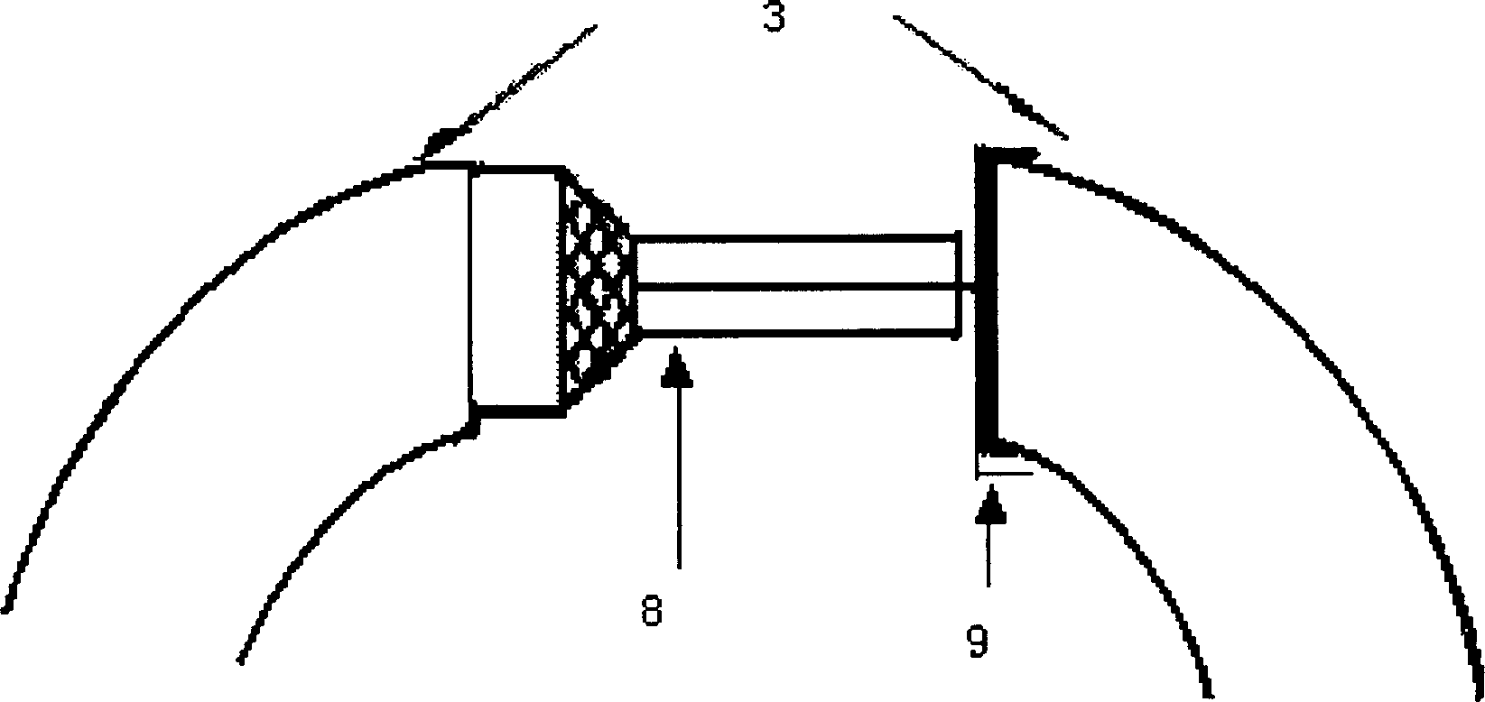
[0019] in the attached figure 1 In the given one-element antenna structure, there are two symmetrical orthogonal loops 3 . The distance between two orthogonal rings 3 is 0.3 to 0.5 times λ 0 , where λ 0 is the operating frequency of the antenna center. And each orthogonal ring 3 is composed of two open rings arranged orthogonally to each other. Each open ring is made of a hollow metal tube, and the circumference of each ring is λ 0 . The two circular rings are short-circuited at one position where they are orthogonal to each other, and the other intersecting position is ...


PUM


Abstract

A quadrature ring antenna is formed by 2n pieces of unit antenna as each unit antenna is prepared by two quadrature rings. It features that distance between two quadrature rings is 0.3 ¿C 0.5 time of lambda o, each quadrature ring is formed by hollow metal tube and formed by two rings with opening on them being arranged in quadrature layout.

Description

technical field [0001] The invention relates to a circular loop antenna, which is especially suitable for television transmission, differential transfer and FM broadcast transmission. The circular loop antenna according to the present invention has a sinusoidal current distribution along the circular loop. Background technique [0002] Chinese invention patent 91103152.9 discloses an orthogonal loop antenna, which has a uniform current distribution along the ring, and its structure is: on the vertical surface of the conventional double-loop antenna, another metal ring with a circumference equal to λ is set at the corresponding position of the ring , the newly established circular rings located on the same side of the middle feed point are connected with parallel wires, each orthogonal ring is insulated, the outermost two sets of lower intersection rings are short-circuited at the outer end, and the innermost two sets of orthogonal rings are connected with λ / 4 feeders And co...

Claims


Application Information

Patent Timeline
Patent Type & Authority Applications(China)
IPC IPC(8): H01Q7/00
Inventor 张金生李柏年朱士涛
Owner LANZHOU UNIVERSITY
Why Eureka
Try Eureka