Bow net analogue test method and its special device

A technology of simulation test and pantograph, which is applied in the direction of railway vehicle testing, etc., can solve the problems of inability to evaluate the current receiving quality of the pantograph and not involving the dynamic performance test of the pantograph.

Inactive Publication Date: 2006-05-24
SOUTHWEST JIAOTONG UNIV
View PDF2 Cites 23 Cited by
  • Summary
  • Abstract
  • Description
  • Claims
  • Application Information

AI Technical Summary

Problems solved by technology

None of them involves the dynamic performance test of the pantograph after the bow and the grid are coupled, so

Method used


Image

  • Bow net analogue test method and its special device
  • Bow net analogue test method and its special device

Examples


specific Embodiment approach

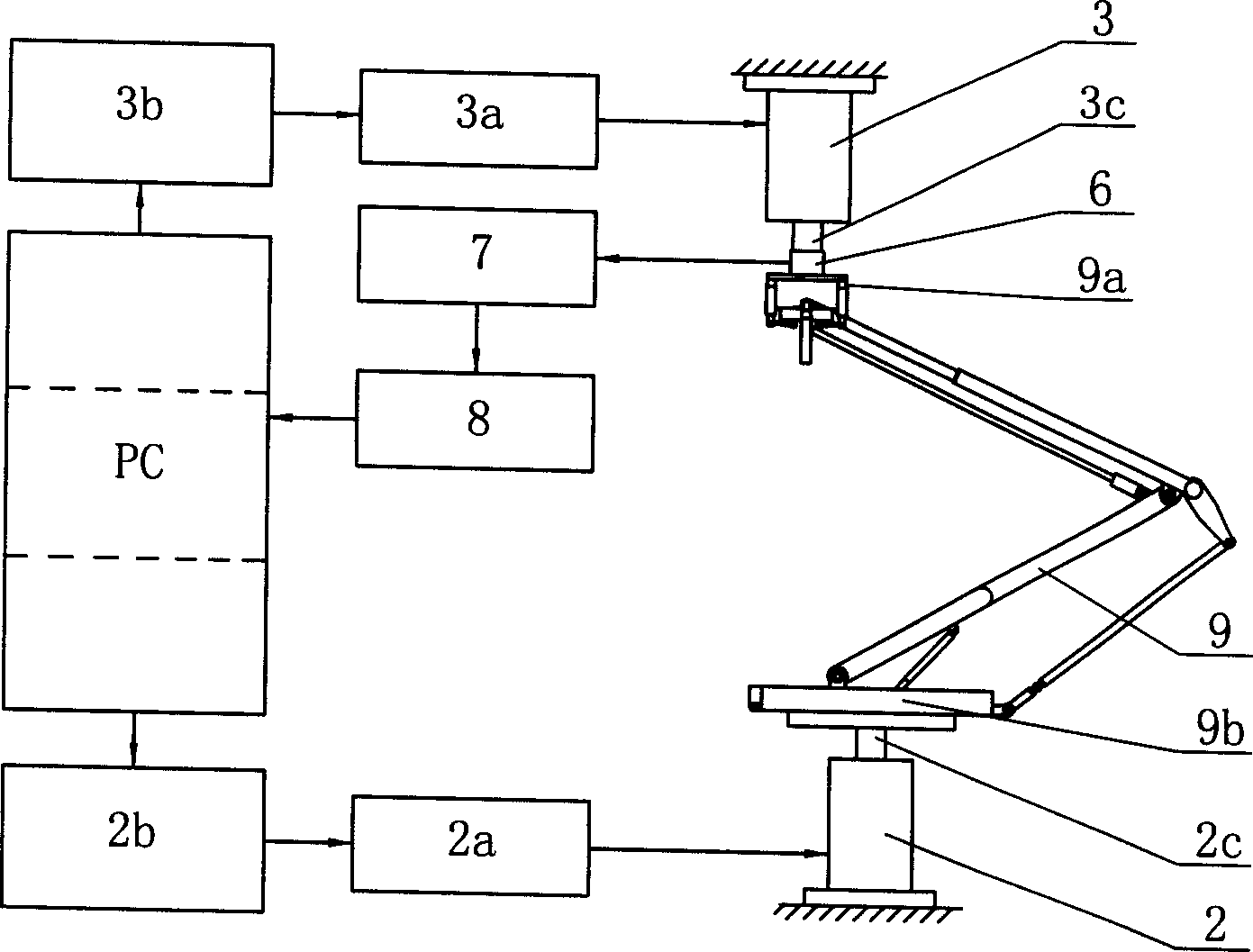
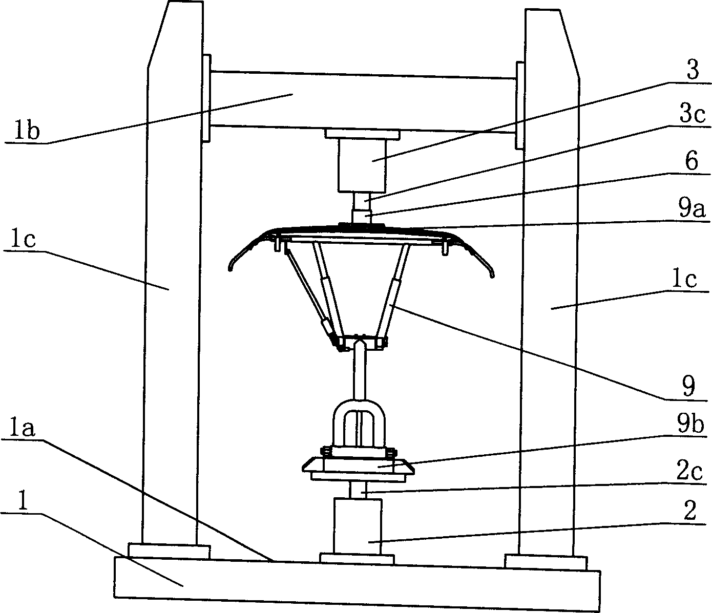
[0025] figure 1 , 2 It is shown that a specific embodiment of the present invention is: a pantograph-catenary simulation test method, which is to test the pantograph-catenary contact pressure of the pantograph 9, the The bow 9 and the dynamic change law of the contact line displacement are tested, in which:

[0026] Vehicle body vibration simulation method: The hydraulic servo vehicle vibration exciter 2 is controlled by the locomotive vibration model signal pre-stored in the computer PC, so that it vibrates according to the law of the model signal when it is excited, and transmits the vibration to the pantograph 9 The base 9b of the locomotive is used to simulate the vibration of the locomotive body that the pantograph 9 is subjected to when the locomotive is actually running.

[0027] Simulation methods for catenary dynamic behavior:

[0028] Initially, an initial static pressure is applied to the pantograph 9 by the hydraulic servo mesh exciter 3 to cause an initial vert...


PUM


Abstract

Under condition for simulating vibration of vehicle body and dynamic action of contact line, the method carries out testing contact pressure between pantograph and bow net as well as dynamic change regulation between pantograph and contact wire. At different speed, and different operating condition of contact line, under dynamic coupling state between pantograph and contact line, the method obtains dynamic change regulation between contact pressure of bow net and vertical displacement of contact point so as to be able to estimate quality of pantograph for receiving current.

Description

Technical field [0001] The invention relates to a pantograph-catenary simulation test method and a special device thereof for testing the dynamic performance of an electric locomotive pantograph and a power supply catenary in a coupled operation state. Background technique [0002] The electric locomotive pantograph is the key component of the locomotive and the only way for the grid to transmit electric energy to the electric locomotive. The dynamic performance of the pantograph has a great influence on the safe operation of the electric locomotive. From the perspective of pantograph-catenary design research and product performance measurement, it is very necessary to simulate and measure pantograph-catenary vibration during pantograph operation. The dynamic performance of the pantograph is mainly manifested in the current receiving quality under the dynamic coupling operation state of the pantograph and the catenary. Usually, the pantograph-catenary contact pressure and t...

Claims


Application Information

Patent Timeline
IPC IPC(8): G01M17/08
Inventor 张卫华吴学杰梅桂明陈良麒马启文
Owner SOUTHWEST JIAOTONG UNIV
Why Eureka
Try Eureka