Light-emitting assembly packaing structure, Backlight module applying it and liquid crystal display device thereof

A technology of light-emitting components and packaging structures, applied in instruments, optics, nonlinear optics, etc., can solve problems such as uneven light sources, and achieve the effect of increasing light incident efficiency and reducing light mixing.

Active Publication Date: 2006-05-24
AU OPTRONICS CORP
View PDF2 Cites 13 Cited by
  • Summary
  • Abstract
  • Description
  • Claims
  • Application Information

AI Technical Summary

Problems solved by technology

[0009] However, the front side of the second reflection mirror 96 reflects all the light emitted by the LED 92 without penetrating any light emitte

Method used


Image

  • Light-emitting assembly packaing structure, Backlight module applying it and liquid crystal display device thereof
  • Light-emitting assembly packaing structure, Backlight module applying it and liquid crystal display device thereof
  • Light-emitting assembly packaing structure, Backlight module applying it and liquid crystal display device thereof

Examples


Example Embodiment

[0074] reference Figure 5a , Figure 5b and Figure 5c , Which shows the light emitting device packaging structure 100 of the first embodiment of the present invention. The light emitting device packaging structure 100 includes a frame 110, at least one light emitting device 120 and a lens 130. The frame 110 has an opening 112, an inner side surface 114, and a bottom 116, wherein the inner side surface 114 may be composed of at least one flat surface and / or at least one curved surface. The light-emitting component 120 may be a light-emitting diode (LED) or other light source with high light intensity and directivity. The light-emitting component 120 is located in the frame 110, for example, the light-emitting component 120 is fixed on the bottom 116 of the frame 110 to emit light. The frame 110 has at least one reflective surface (not labeled), which can be located on the bottom 116 and / or the inner side 114 of the frame 110 to reflect the light emitted by the light-emitting comp...


PUM


Abstract

The packaging structure includes a frame, at least a luminescence subassembly and a lens. The frame possesses an opening, a medial surface and a base. Being located inside the frame, the luminescence subassembly is in use for sending out light beam. Being positioned above the luminescence subassembly, the lens possesses a surface and at least a groove. The said surface is back on to the luminescence subassembly; and being located on the surface, the groove faces to the luminescence subassembly.

Description

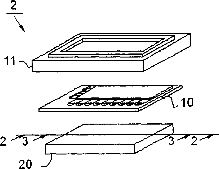
technical field [0001] The invention relates to a packaging structure of a light-emitting component, in particular to a packaging structure of a light-emitting component with a lens, and the lens has a groove to make the light with strong directivity of the light-emitting component produce total reflection. Background technique [0002] With the advancement of electronic technology, especially the prevalence of portable electronic products in daily life, the demand for thin, light, small and low power consumption displays is increasing day by day. Liquid crystal display (Liquid Crystal Display; LCD) is often used in such electronic products due to its advantages of low power consumption, low heat generation, light weight, and non-luminous display, and has even gradually replaced traditional cathodes. Ray tube monitor. [0003] Such as figure 1 As shown, it shows the structure of the existing liquid crystal display. Generally speaking, the liquid crystal display 2 includes...

Claims


Application Information

Patent Timeline
IPC IPC(8): G02F1/1335G02F1/1333
Inventor 刘邦炫林玫芬
Owner AU OPTRONICS CORP
Why Eureka
Try Eureka