Display device with thin-film solar cells

A technology of solar cells and display devices, applied in photovoltaic power generation, optics, instruments, etc., can solve problems such as inability to effectively overcome thin design

Pending Publication Date: 2021-12-07
GIANTPLUS TECH
View PDF7 Cites 0 Cited by
  • Summary
  • Abstract
  • Description
  • Claims
  • Application Information

AI Technical Summary

Problems solved by technology

[0006] Since the components required by the conventional display device 1 already have a certain thickness in terms of structural design, if combined wit

Method used


Image

  • Display device with thin-film solar cells
  • Display device with thin-film solar cells
  • Display device with thin-film solar cells

Examples


Embodiment Construction

[0069] In order to make the structural features of the present invention and the achieved effects have a further understanding and recognition, preferred embodiments and detailed descriptions are specially used, which are described as follows:

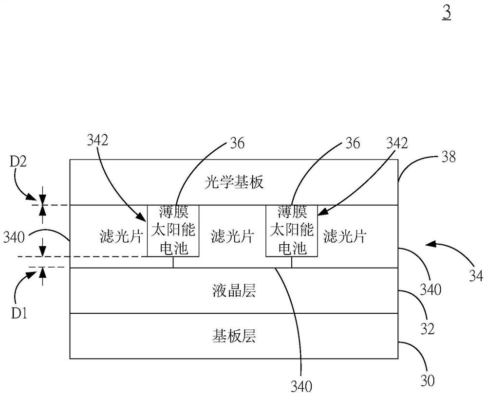
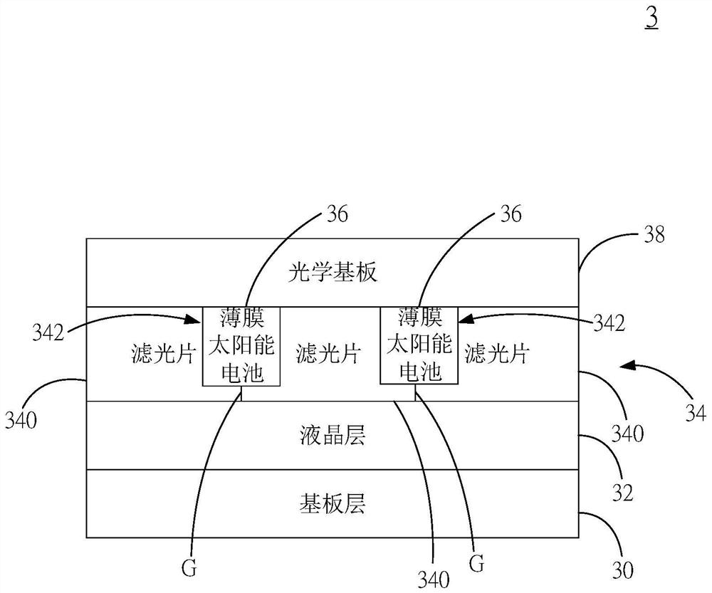
[0070] see figure 2 , which is a schematic structural view of the first embodiment of the display device with thin-film solar cells of the present invention. As shown in the figure, the display device 3 with thin-film solar cells of the present invention includes: a substrate layer 30; a liquid crystal layer 32 disposed on the substrate layer 30; a filter layer 34 including a plurality of filters 340, each One optical filter 340 is arranged adjacent to each other and is arranged on the liquid crystal layer 32, and the adjoining place of each optical filter 340 includes an accommodation chamber 342; and an optical substrate 38 disposed on the filter layer 34 .

[0071] The above-mentioned substrate layer 30 is a layer body composed o...


PUM


Abstract

The invention aims to disclose a display device with thin-film solar cells. The display device comprises a substrate layer, a liquid crystal layer, a filter layer, a plurality of thin-film solar cells and an optical substrate, the thin-film solar cell is arranged at the adjacent position of the plurality of optical filters included in the optical filter layer, so that the arrangement of related elements is reduced, the effect of original elements is replaced, and the overall thickness of the display device is reduced.

Description

technical field [0001] The present invention relates to a display device, in particular to a display device with a thin-film solar cell. Background technique [0002] After entering the 21st century, technology began to develop by leaps and bounds. More and more electronic products are popularized in daily necessities. Liquid Crystal Display (LCD for short) is one of the representative products. [0003] Although electronic products have the practicability of their own functions, there are still some deficiencies to be improved. As people in various fields continue to improve their professional skills in their own fields, it is bound to be able to improve the design of various products in the future and approach the ideal. [0004] see figure 1 , which is a schematic diagram of a conventional display device with a solar cell structure. As shown in the figure, a conventional display device 1 with a solar cell structure includes a substrate layer 10 , a liquid crystal layer...

Claims


Application Information

Patent Timeline
IPC IPC(8): G02F1/1333G02F1/1335
CPCG02F1/1333G02F1/133514G02F1/133512Y02E10/50
Inventor 吴哲耀周凯茹康镇玺江宜达唐安迪王维廉刘康志
Owner GIANTPLUS TECH
Why Eureka
Try Eureka