
Filter assembly utilizing carbon block and pleated filter element

A filter assembly, filter element technology, applied in the direction of cartridge filter, filtration separation, filtration treatment, etc., can solve problems such as disclosure or proposal

Inactive Publication Date: 2006-05-24
3M INNOVATIVE PROPERTIES CO
View PDF10 Cites 11 Cited by
  • Summary
  • Abstract
  • Description
  • Claims
  • Application Information

AI Technical Summary

Problems solved by technology

While the above references disclose combined filter elements for inclusion in filter devices, they do not disclose or suggest, individually or in combination, the use of the carbon block filter element and the radially outer filter element surrounding the carbon block filter element described and claimed in the present invention. Surface pleated filter element

Method used

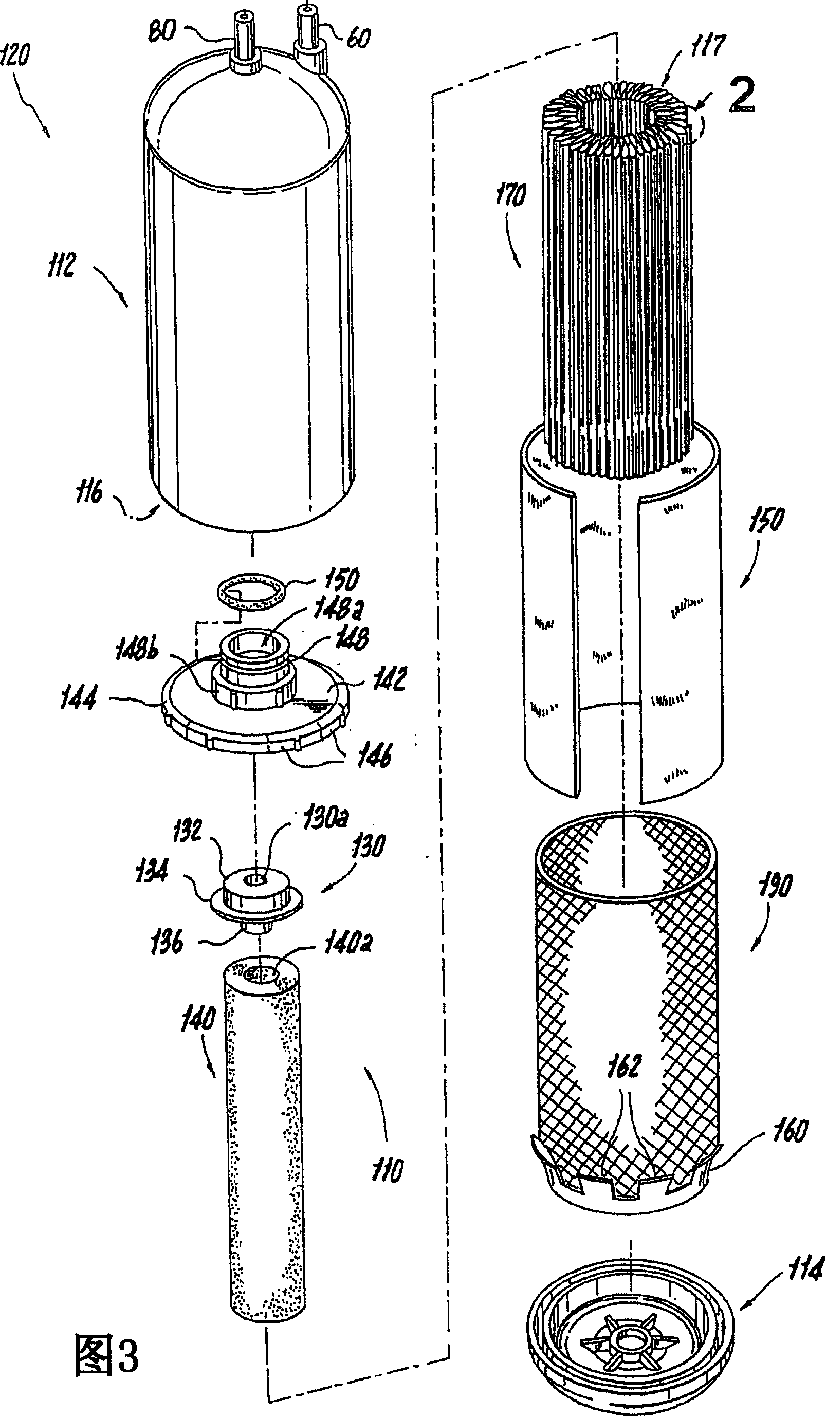

Image

  • Filter assembly utilizing carbon block and pleated filter element
  • Filter assembly utilizing carbon block and pleated filter element
  • Filter assembly utilizing carbon block and pleated filter element

Examples


Embodiment Construction

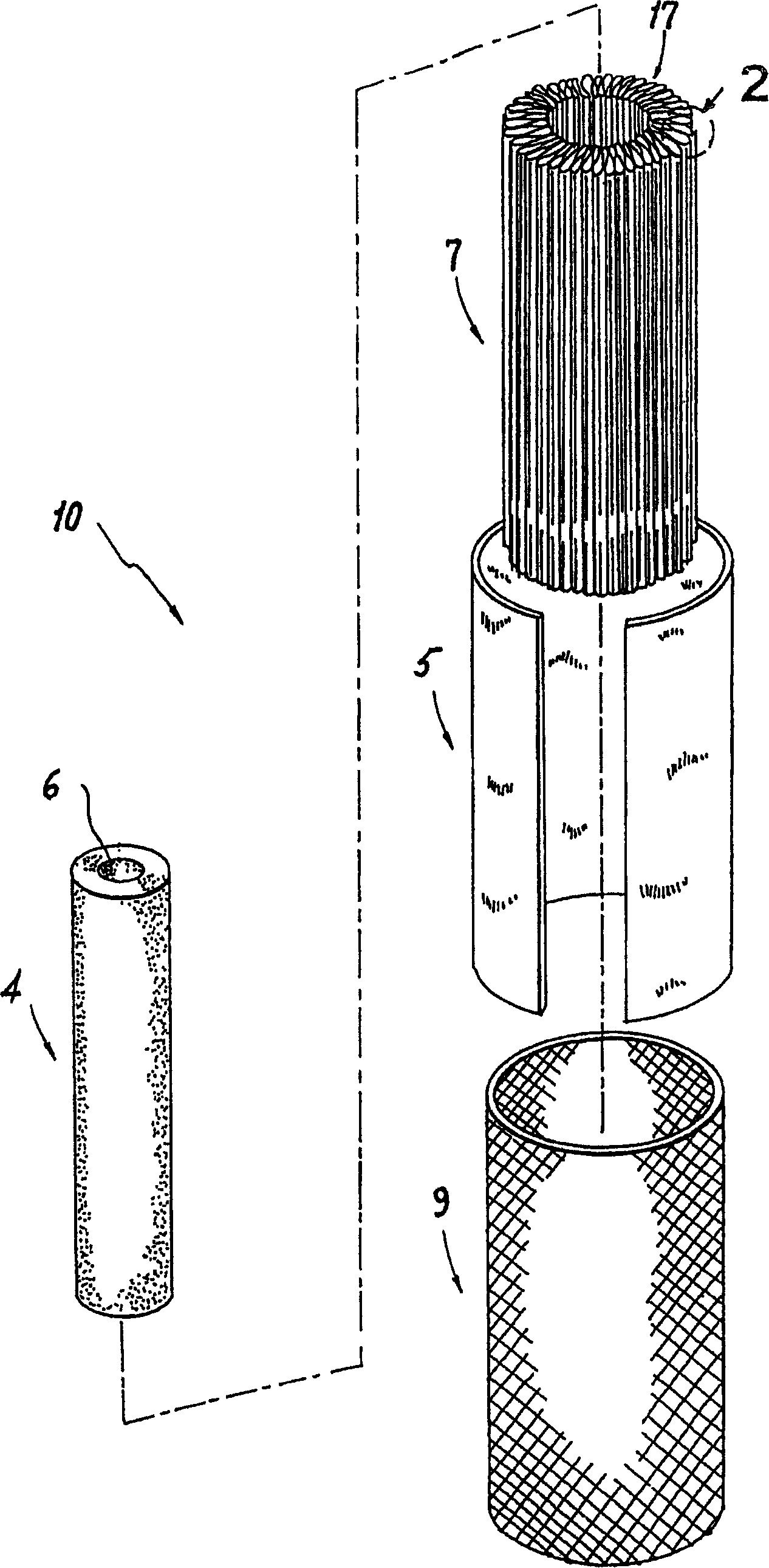
[0028] Referring to the accompanying drawings, wherein like reference numerals denote like structural elements of the filtration device described herein, figure 1 An exemplary filter assembly constructed in accordance with the present invention is shown generally at 10 . Such as figure 1 As shown, the filter assembly 10 includes a generally cylindrical carbon block filter element 4 having an axial cavity 6 extending through the filter element 4 or not. Such carbon block filter elements can be produced according to, for example, US Patent Nos. 5,928,588 and 5,882,517 to Wei-Chih Chen et al. Both of these patents have been assigned to Cuno Corporation, the contents of which are incorporated herein by reference.

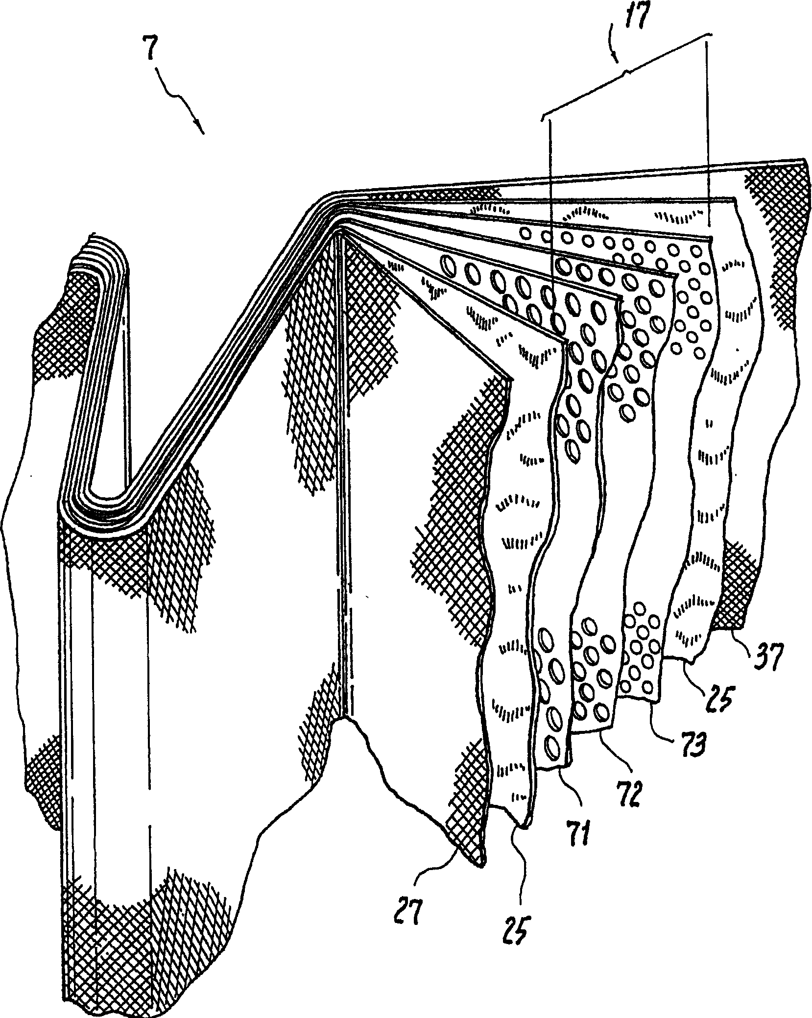
[0029] Such as figure 1 As shown, the filter assembly 10 also includes a generally cylindrical pleated filter element 7 disposed around the outer circumference of the carbon block filter element 4 . An exemplary pleated filter element 7 suitable for use in embodimen...


PUM


Abstract

A filter assembly for a filter cartridge is disclosed, the filter assembly comprising a generally cylindrical carbon block filter element and a generally cylindrical carbon block filter element disposed around the radially outer surface of the carbon block filter element. Pleated filter element. The filter assembly has an outlet communicating with the cavity of the carbon block filter element so that the filtrate first flows through the pleated filter element, enters the carbon block filter element through the radially outer surface of the carbon block filter element, and radially Diffusion into the axial cavity of the carbon block filter element, and then flow axially along the central cavity of the carbon block filter element, and exit the central cavity of the carbon block filter element through the outlet.

Description

technical field [0001] The present invention relates to filtration devices, and more particularly to filter assemblies configured to fit within filter cartridges. A filter assembly according to the present invention may comprise a carbon block filter element and a pleated filter element surrounding a radially outer surface of the carbon block filter element. Background technique [0002] In most parts of the world, drinking or tap water contains considerable amounts of harmful or objectionable chemicals, suspended particulate matter and microorganisms. In various environments, these contaminants must be removed before the water is used. While municipal water treatment plants attempt to address this problem, many individuals and organizations find this effort insufficient and use on-site water filters. Such water filters are often incorporated into appliances such as ice makers in refrigerators, or water dispensers. [0003] Filter elements containing activated carbon are ...

Claims


Application Information

Patent Timeline
IPC IPC(8): B01D36/00B01D19/00B01D27/06B01D35/30B01D61/18B01D61/20C02F1/00C02F1/28C02F1/44
CPCB01D19/0031B01D35/30B01D61/18C02F1/001C02F1/283C02F1/44C02F2201/006
Inventor 托马斯·哈姆林马丁·布拉泽劳伦斯·W·巴塞特
Owner 3M INNOVATIVE PROPERTIES CO
Learn More