Display and mobile device

A display device and display panel technology, applied to static indicators, instruments, etc., can solve problems such as malfunctions

Inactive Publication Date: 2006-06-07
SANYO ELECTRIC CO LTD
View PDF0 Cites 14 Cited by
  • Summary
  • Abstract
  • Description
  • Claims
  • Application Information

AI Technical Summary

Problems solved by technology

However, the flexible printed circuit board 212 for backlight, the diffusion sheet 211, and the glass substrate 215 disposed between the LED 207 and the driver IC 218 are light-transmit

Method used


Image

  • Display and mobile device
  • Display and mobile device
  • Display and mobile device

Examples


Embodiment Construction

[0096] Now referring to the accompanying drawings, the embodiment of the present invention is described as follows:

[0097] (first embodiment)

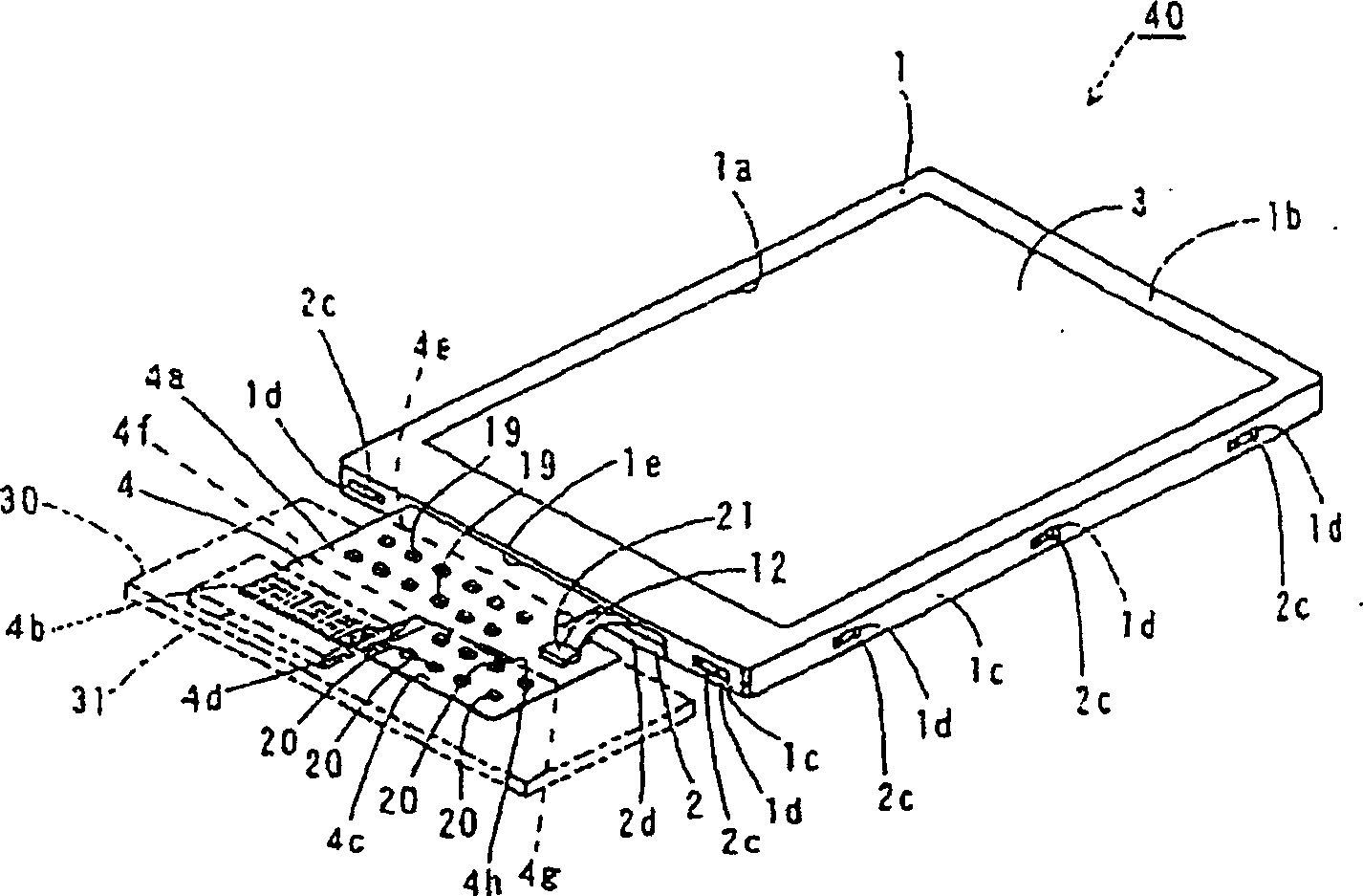
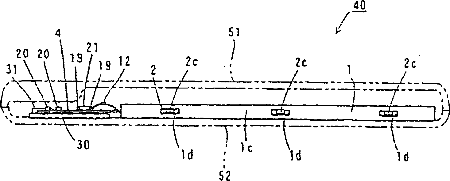
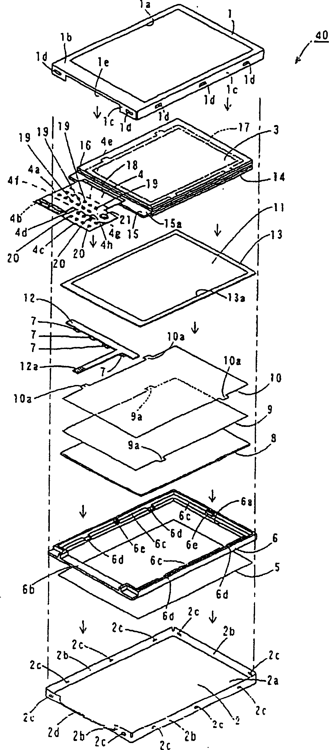
[0098] First, refer to Figures 1 to 7 A liquid crystal display unit (LCD unit) 40 according to a first embodiment of the present invention will be described. In the first embodiment, the liquid crystal display device 40 which is an example of the display device of the present invention will be described.

[0099] The liquid crystal display device of the first embodiment is as follows figure 1 and 2 As shown, it has: a metal upper frame 1 and a lower frame 2 made of metal plates; an upper polarizing plate 3 arranged inside the upper frame 1 and the lower frame 2 (refer to figure 1 ); and a flexible printed circuit board (FPC) 4 for the panel. The flexible printed circuit board (FPC) 4 for panels is an example of the flexible printed circuit board of this invention. as well figure 2 As shown, the liquid crystal display device ...


PUM


Abstract

The present invention provides a display device capable of suppressing light from a light source for backlight from leaking to the display area side through the inner side surface of the frame. The display device includes: a display panel including a display area; a frame for accommodating the display panel; a backlight light source arranged on the back side of the display panel; The light shielding portion is provided on the side end surface side of the display panel plane and partially protruded to include a light leakage suppression portion that suppresses the light source for the backlight.

Description

technical field [0001] The present invention relates to a display device and a portable device, and more particularly to a display device and a portable device having a display panel. Background technique [0002] A display device including a display panel is known, as disclosed in Japanese Patent No. 3322629. This publication discloses a structure of a liquid crystal display device (Liquid Crystal Display, LCD) provided with wiring. On the other hand, conventional liquid crystal display devices equipped with a display panel have a structure in which a light-shielding portion (black-mask) is provided to cover a region other than a display region such as a wiring pattern of the display panel. [0003] 29 is a perspective view showing the overall configuration of a liquid crystal display device (display device) provided with a light-shielding portion covering a wiring pattern of a display panel in a conventional example. FIG. 30 is an exploded perspective view of the convent...

Claims


Application Information

Patent Timeline
IPC IPC(8): G02F1/133G09G3/36
Inventor 奥田辰美
Owner SANYO ELECTRIC CO LTD
Why Eureka
Try Eureka