Thermoelectric direct conversion device

A conversion device, direct technology, applied to thermoelectric devices, thermoelectric device components, circuits, etc., can solve the problem of poor mechanical or electrical characteristics of high-temperature electrodes 5 and low-temperature electrodes 6, and thermoelectric direct conversion performance. Thermoelectric direct conversion device 1 generates electricity poor performance

Inactive Publication Date: 2006-06-07
KK TOSHIBA
View PDF1 Cites 25 Cited by
  • Summary
  • Abstract
  • Description
  • Claims
  • Application Information

AI Technical Summary

Problems solved by technology

That is, the chemical elements in the high-temperature electrode 5 or the low-temperature electrode 6 may diffuse into the thermoelectric direct conversion semiconductor pair 4 and cause the thermoelectric direct conversion performance of the thermoelectric direct conversion semiconductor pair 4 and the power generation performance of the thermoelectric direct conversion device 1 to deteriorate.
[0016] Conversely, the chemical elements in the thermoelectric direct conversion semiconductor pair 4 may diffuse into the high-temperature electrode 5 and the low-temperature electrode 6, resulting in deterioration of the mechanical or electrical properties of the high-temperature electrode 5 and low-temperature electrode 6

Method used


Image

  • Thermoelectric direct conversion device
  • Thermoelectric direct conversion device
  • Thermoelectric direct conversion device

Examples


Embodiment Construction

[0030] Embodiments of the thermoelectric direct conversion device according to the present invention will be described below with reference to the accompanying drawings, wherein the same parts are denoted by the same symbols.

[0031] (1) Structure of the thermoelectric direct conversion device according to the first embodiment

[0032] FIG. 1 shows a thermoelectric direct conversion device according to a first embodiment of the present invention.

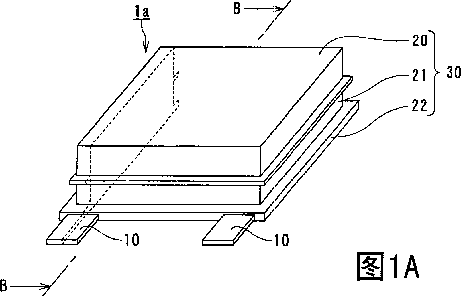
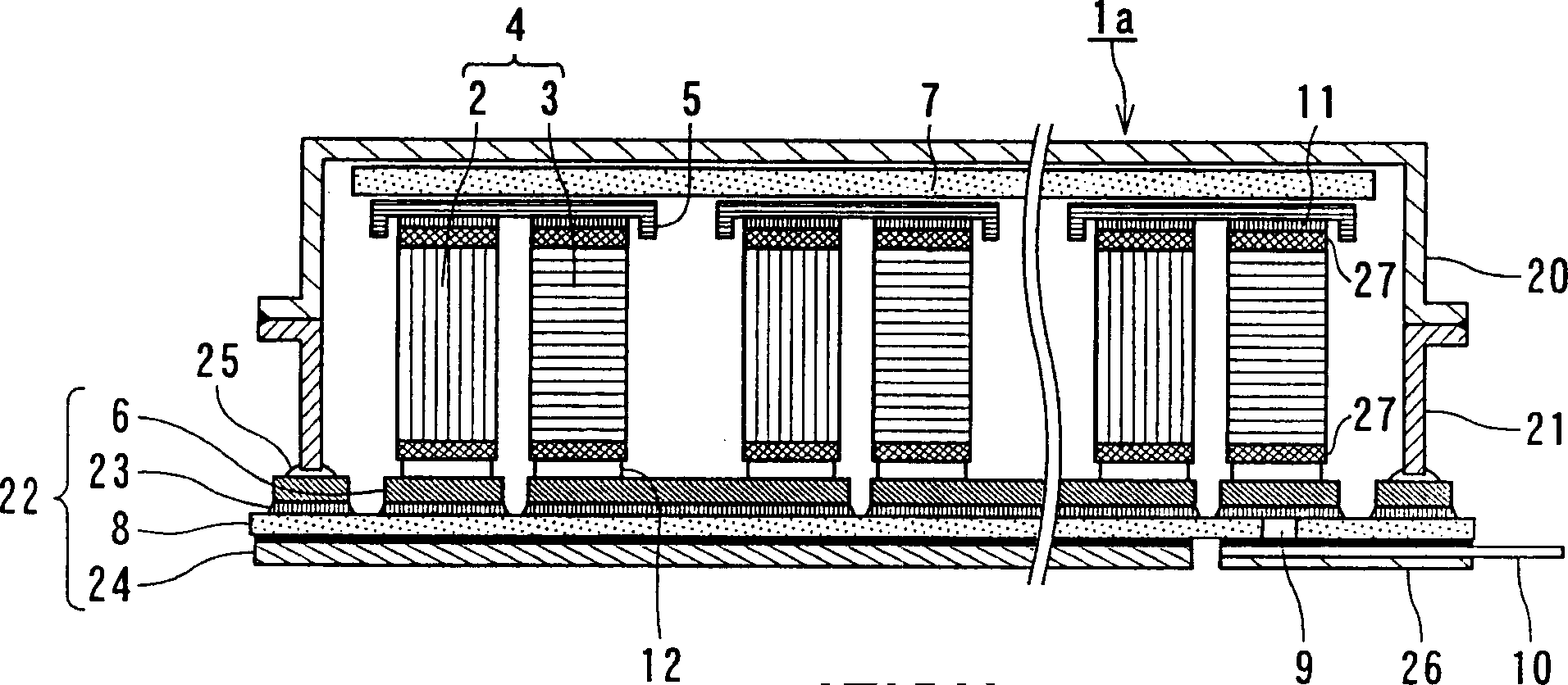
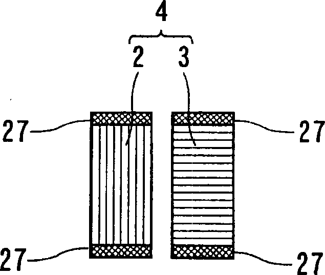
[0033] Fig. 1A is a schematic perspective view of a thermoelectric direct conversion device 1a according to a first embodiment of the present invention. Figure 1B is a schematic cross-sectional view of the thermoelectric direct conversion device 1a along the line B-B in FIG. 1A. Figure 1C is a schematic diagram of the thermoelectric direct conversion semiconductor pair 4 shown in the thermoelectric direct conversion device 1a.

[0034] As shown in Figure 1, the thermoelectric direct conversion device 1a includes a plurality of ...


PUM


Abstract

A thermoelectric direct conversion device, which is formed with a plurality of thermoelectric direct conversion semiconductor pairs, wherein each thermoelectric direct conversion semiconductor pair includes a p-type semiconductor and an n-type semiconductor; a plurality of high-temperature electrodes and a plurality of low-temperature electrodes, wherein each The high-temperature electrode and the low-temperature electrode are electrically connected to the p-type semiconductor and the n-type semiconductor; a high-temperature insulating plate and a low-temperature insulating plate, wherein each of the high-temperature insulating plate and the low-temperature insulating plate respectively passes through the plurality of high-temperature electrodes or the plurality of The low temperature electrode is thermally connected to the plurality of thermoelectric direct conversion semiconductor pairs; at least one diffusion barrier layer is located between the high temperature electrode or the low temperature electrode and the thermoelectric direct conversion semiconductor pair, and the whole device is hermetically sealed in a vacuum chamber containing Or in an airtight shell of an inert gas atmosphere, thereby preventing the diffusion between the electrode and the semiconductor pair to provide a thermoelectric conversion device that exhibits excellent power generation performance over a long period of time.

Description

technical field [0001] The present invention relates to a thermoelectric direct conversion device, in particular to a thermoelectric direct conversion device which can maintain the mechanical or electrical characteristics of its components and maintain excellent conversion efficiency for a long time. Background technique [0002] The unprecedented rapid growth of energy consumption in recent years has led to the emission of greenhouse gases such as carbon dioxide (CO 2 ) caused global warming. In order to protect the global environment, develop a method that can reduce CO 2 Emissions of energy have become imperative on a global scale. Under such circumstances, waste heat has been recovered and reused on a large scale, mainly from the viewpoint of energy conservation. Furthermore, the reuse of waste heat even on a small to medium scale has received attention. [0003] However, waste heat on a small to medium scale is relatively low in calories, even...

Claims


Application Information

Patent Timeline
Patent Type & Authority Applications(China)
IPC IPC(8): H01L35/00H01L35/02H01L35/28
CPCH10N10/81H10N10/17
Inventor 常冈治近藤成仁岩抚直和原昭浩馆山和树
Owner KK TOSHIBA
Why Eureka
Try Eureka