Method for driving a movable part of a piece of furniture

A furniture and sports technology, applied in the field of drawers, can solve the problems of increasing the production cost of furniture, increasing the structural cost of furniture, etc.

Active Publication Date: 2006-06-14
JULIUS BLUM GMBH
View PDF0 Cites 2 Cited by
  • Summary
  • Abstract
  • Description
  • Claims
  • Application Information

AI Technical Summary

Problems solved by technology

Therefore try to take various safety measures to eliminate this danger in the prior art, these measures all have the shortcoming of increasing furniture structure cost and raising furniture production cost

Method used


Image

  • Method for driving a movable part of a piece of furniture
  • Method for driving a movable part of a piece of furniture
  • Method for driving a movable part of a piece of furniture

Examples


Embodiment Construction

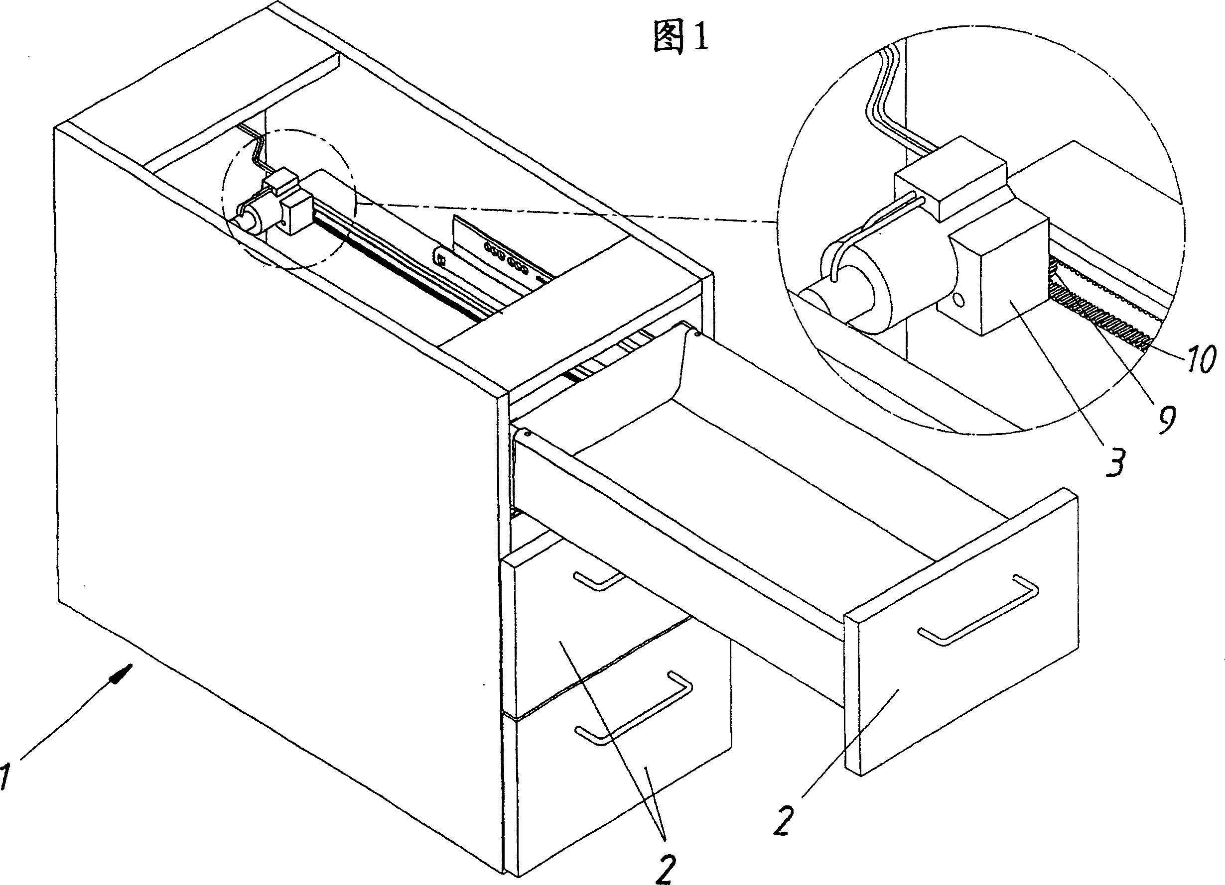
[0036] FIG. 1 schematically shows a piece of furniture 1 with a plurality of movable furniture parts 2 , the uppermost furniture part 2 being drawn out. The drive 3 , which is an electric motor in the exemplary embodiment, as well as the rollers 9 and the toothed belt 10 guided thereon can also be seen in the detailed illustration. The drive device 3 drives the rollers 9 and thus the toothed belt 10 . The movable furniture part 2 is moved by means of a toothed belt 10 in a known manner. In the exemplary embodiment shown in FIG. 1, the drive device 3 includes a current measuring device (not shown) for determining the force exerted by the drive device 3 on the movable furniture part 2 according to the provisions of the invention.

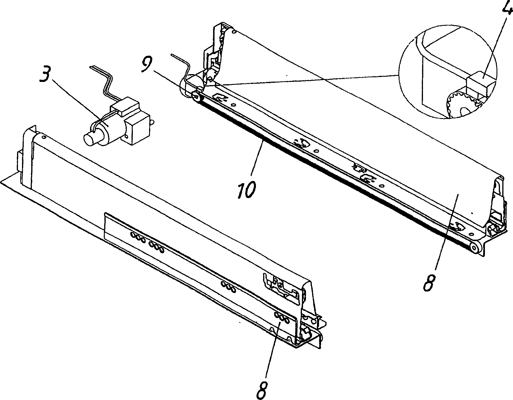
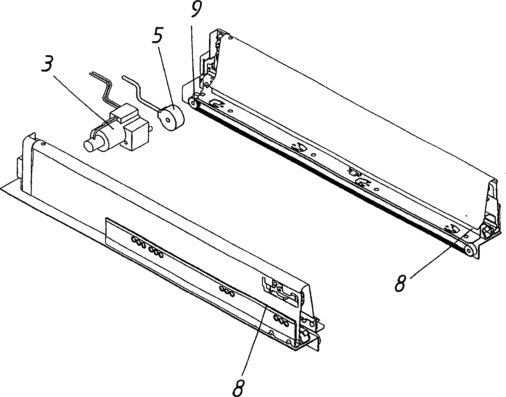
[0037] figure 2 The embodiment shown differs from the embodiment in FIG. 1 in that the force is determined not by means of a current measuring device integrated in the drive 3 but by means of a mechanical force sensor 4 in contact with the toothed ...


PUM


Abstract

The invention relates to a method for driving a movable furniture part, in particular a drawer, by means of an in particular electric drive, wherein at least a section of the path (S) to be covered by the movable furniture part (2) is (S2), the force exerted by the driving device (3) on the movable furniture part (2) is adjusted to a predetermined value.

Description

technical field [0001] The invention relates to a method for driving a movable furniture part, in particular a drawer, by means of an especially electric drive. Background technique [0002] In the case of movable furniture parts, the risk of injury to the user already present in the case of non-driven movable furniture parts is significantly increased or the movable furniture part due to the opening of the movable furniture part Risk of damage to movable furniture parts due to collision with objects during travel. Therefore try to take various safety measures to eliminate this danger in the prior art, these measures all have the shortcoming that increases furniture structure cost and raises furniture production cost. Contents of the invention [0003] The object of the present invention is to create a method for driving movable furniture parts which overcomes these disadvantages. [0004] According to the invention, measures are taken for this purpose to adjust the forc...

Claims


Application Information

Patent Timeline
Patent Type & Authority Applications(China)
IPC IPC(8): A47B88/04
CPCE05Y2900/20E05F15/643A47B88/457
Inventor E·胡贝尔U·舍夫克内希特
Owner JULIUS BLUM GMBH
Why Eureka
Try Eureka