Air conditioning device
A technology of air conditioning device and detection device, which is applied in the directions of space heating and ventilation, heating mode, lighting and heating equipment, etc., can solve the problem of air intake pressure drop, insufficient indoor heating capacity, and increased frequency of starting/stopping of air conditioners, etc. problem, to achieve the effect of delayed frosting
- Summary
- Abstract
- Description
- Claims
- Application Information
AI Technical Summary
Problems solved by technology
Method used
Image

Examples
Embodiment 1
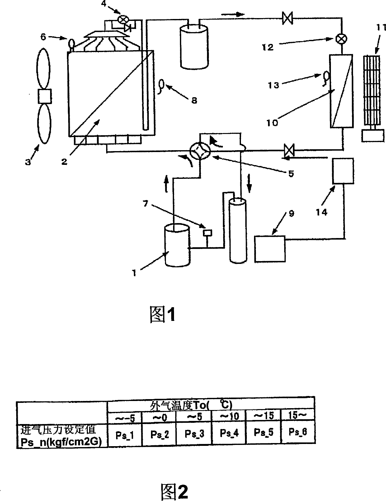
[0025] FIG. 1 shows a schematic diagram of the freezing loop in Example 1.
[0026] The refrigerating cycle shown in Fig. 1 includes an outdoor unit and an indoor unit, and the outdoor unit includes: a power variable compressor 1; an outdoor side heat exchanger 2; an outdoor blower 3; Expansion valve 4, four-way valve 5 for switching cooling operation and heating operation; outdoor heat exchanger temperature detection device 6; intake pressure detection device 7; outside air temperature detection device 8; and outdoor unit control device 9. The indoor unit includes: an indoor side heat exchanger 10 ; an indoor blower 11 ; an electric expansion valve 12 for reducing pressure; an indoor unit suction air temperature detection device 13 ; and an indoor unit control device 14 .
[0027] FIG. 2 is an intake pressure set value table for explaining the operation control method of the present invention, in which a prescribed intake pressure set value is assigned for each outside air te...
Embodiment 2
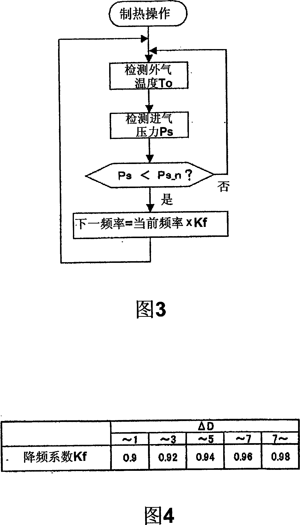
[0033] 4 is a frequency reduction coefficient table for explaining the operation control method of the present invention, in which a predetermined frequency reduction coefficient is assigned in advance for each temperature difference between a remote controller set temperature and indoor suction air temperature.
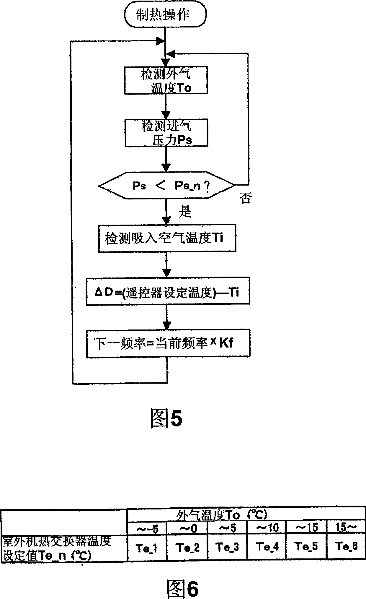
[0034] FIG. 5 is an operation flowchart for explaining the operation control method of the present invention.
[0035] As in Embodiment 1, when the heating operation is performed, the intake pressure Ps is first detected by the intake pressure detection device 7 , and the outside air temperature To is detected by the outside air temperature detection device 8 .
[0036] Then, the intake air temperature Ti is detected by the indoor intake air temperature detection device, and then the temperature difference ΔD between the remote control setting temperature and Ti is calculated, and the frequency reduction coefficient Kf is obtained from Figure 4 .
[0037] If the inta...
Embodiment 3
[0040] 6 is an outdoor unit heat exchanger temperature setting value table for explaining another operation control method of the present invention, in which a prescribed outdoor unit heat exchanger temperature setting value is assigned for each outside air temperature.
[0041] FIG. 7 is an operation flowchart for explaining the operation control method in the present invention.
[0042] During the heating operation, first, the outdoor heat exchanger temperature Te is detected by the outdoor heat exchanger temperature detection device 6 , and the outside air temperature To is detected by the outside air temperature detection device 8 .
[0043] Next, refer to FIG. 7 to obtain the corresponding outdoor unit heat exchanger temperature setting values Te_1~Te_6 from the outside air temperature, and then compare them with the actual outdoor unit heat exchanger temperature Te.
[0044] If the temperature Te of the heat exchanger of the outdoor unit is lower than the temperature s...
PUM
 Abstract
Description
Claims
Application Information