LED drive device

A technology of light-emitting diodes and driving devices, which is applied in optics, nonlinear optics, instruments, etc., and can solve the problems of different luminous brightness, uneven and different brightness of backlight modules, etc.

Inactive Publication Date: 2006-06-21
QUANTA COMPUTER INC
View PDF0 Cites 20 Cited by
  • Summary
  • Abstract
  • Description
  • Claims
  • Application Information

AI Technical Summary

Problems solved by technology

[0004] However, the cut-in voltage of each light-emitting diode is different, so the current Ia and Ib of the two parallel-connected light-emitting diode series S1 and S2 are different, so that the current Ia and Ib of each light-emitting diode series S1 and S2 are different. The brightness of the light is not the same, and the brightness generated by the e

Method used


Image

  • LED drive device
  • LED drive device
  • LED drive device

Examples


Embodiment Construction

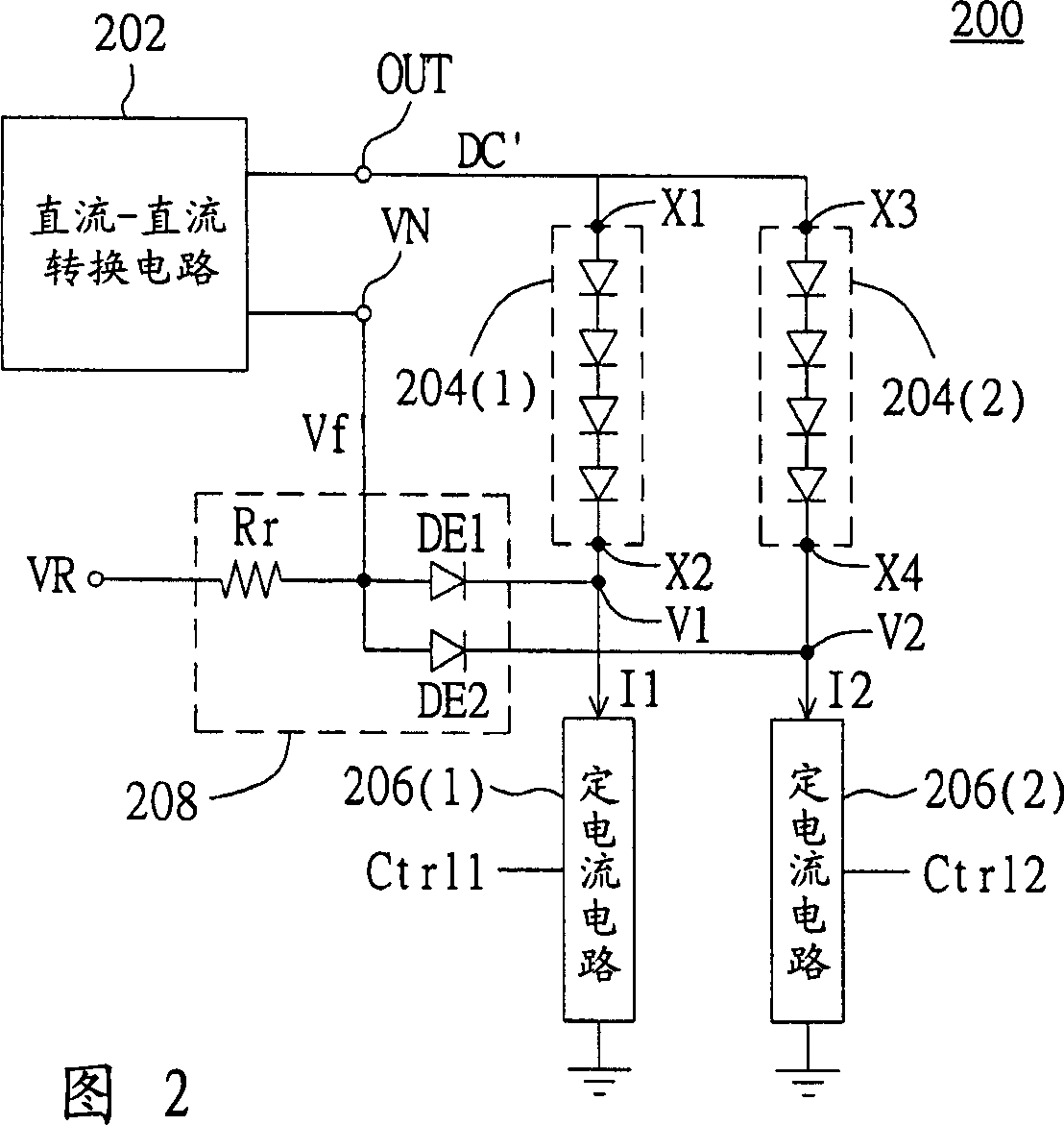
[0024] The purpose of the present invention is to make each series of LEDs produce the same brightness. That is, the current flowing through each string of LED strings is the same. Therefore, each LED string is driven by a constant current circuit, such as the first LED string is driven by the first constant current circuit, and the second LED string is driven by the second constant current circuit. Driving, by making the first constant current circuit and the second constant current circuit output the same magnitude of current, so as to achieve the same current of each string of light emitting diodes.

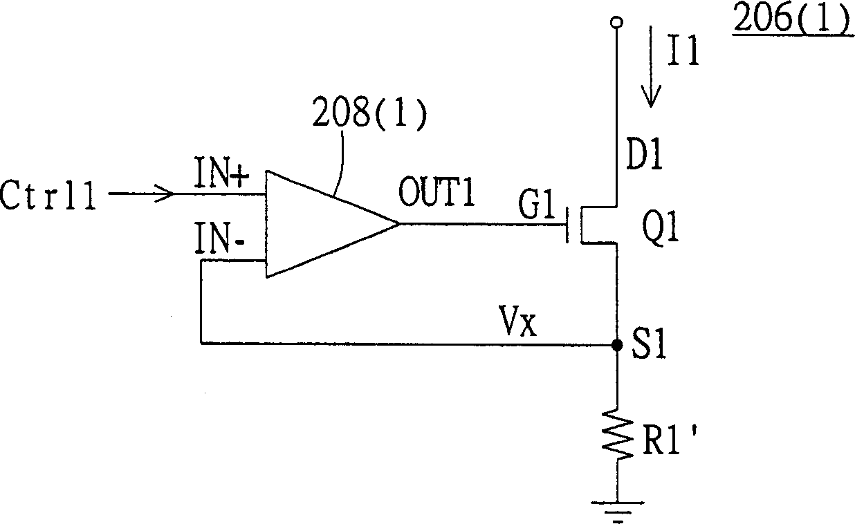
[0025] Referring to FIG. 2 , it shows a circuit diagram of an LED driving device according to a preferred embodiment of the present invention. The LED driving device 200 includes a DC-DC converter 202 , N sets of LED strings 204 , N constant current circuits 206 and feedback circuits 208 , where N is a positive integer. Each of the N sets of LED strings has an LED input end ...


PUM


Abstract

The invention discloses a luminescent diode driving device, which comprises the following parts: DC-DC transducer, the first and second luminescent diode tandem, the first and second current circuit and feedback circuit, wherein the DC-DC transducer outputs the DC voltage to one end of the first and second luminescent diode tandem according to the feedback voltage, which generates the first electric potential and second electric potential on the other end of the first and second luminescent diode tandem; the first and second current circuit couples the other end of the first and second luminescent diode tandem separately, which outputs the first current and second current corresponding to the first control signal and second control signal; the first and second current is applied to drive the first and second luminescent diode tandem; the feedback circuit adapts the lower electric potential in the first or second electric potential as the feedback voltage.

Description

technical field [0001] The invention relates to a light-emitting diode driving device, in particular to a light-emitting diode driving device with a constant current circuit. Background technique [0002] The liquid crystal display uses a backlight module to provide the light source required by the liquid crystal panel, and the light source can be generated by a light emitting diode (Light emitted diode). The light-emitting diode generates corresponding luminous brightness according to the magnitude of the current flowing when it is turned on. Therefore, the brightness of light emitting diodes is directly proportional to the magnitude of the current flowing through them. [0003] In order to achieve the required brightness, the backlight module needs to be composed of multiple LEDs to generate sufficient brightness. Referring to FIG. 1 , it is a conventional LED driving device. As can be seen from FIG. 1 , the DC-DC converter 102 outputs a DC voltage DC to drive the two L...

Claims


Application Information

Patent Timeline
IPC IPC(8): G02F1/1335G09G3/32
Inventor 陈升峰
Owner QUANTA COMPUTER INC
Why Eureka
Try Eureka