Capacitor based force sensor

A capacitive, capacitive technology used in instruments, measuring forces, measuring devices, etc.

Inactive Publication Date: 2006-06-21
3M INNOVATIVE PROPERTIES CO
View PDF4 Cites 25 Cited by
  • Summary
  • Abstract
  • Description
  • Claims
  • Application Information

AI Technical Summary

Problems solved by technology

[0009] The prior art does not disclose a sensor capable of detecting different force ranges from very light to impact forces at the level of accuracy required by many contact applications, but still dictates size limitations for certain force-based applications

Method used


Image

  • Capacitor based force sensor
  • Capacitor based force sensor
  • Capacitor based force sensor

Examples


Embodiment Construction

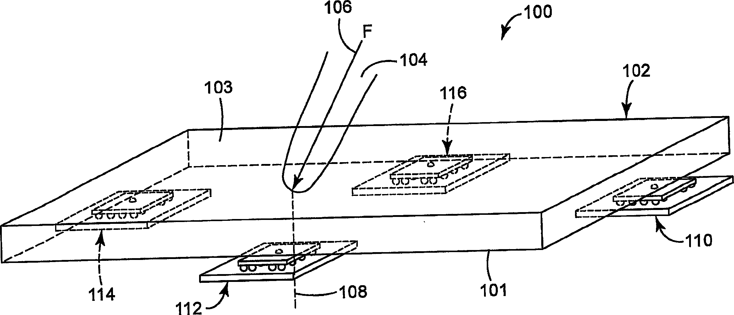
[0019] According to one aspect of the present invention, a novel capacitive force trigger device is provided. As described in more detail below, the device of the present invention can provide a more reliable, sensitive and accurate characterization of the forces acting on the device. These improved performance of the device when using the device in small applications such as mobile handheld devices, as well as in larger applications such as computer monitors and other applications requiring high levels of touch and / or force sensitivity may be particularly advantageous. We predict that the invention may be more broadly applicable to any application in which an input force must be characterized by, for example, the amplitude, duration, acceleration or velocity of the input force.

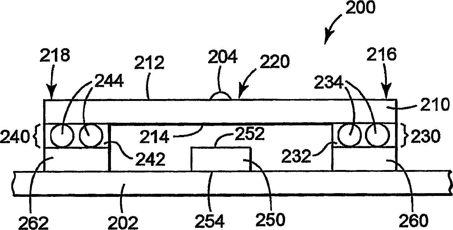
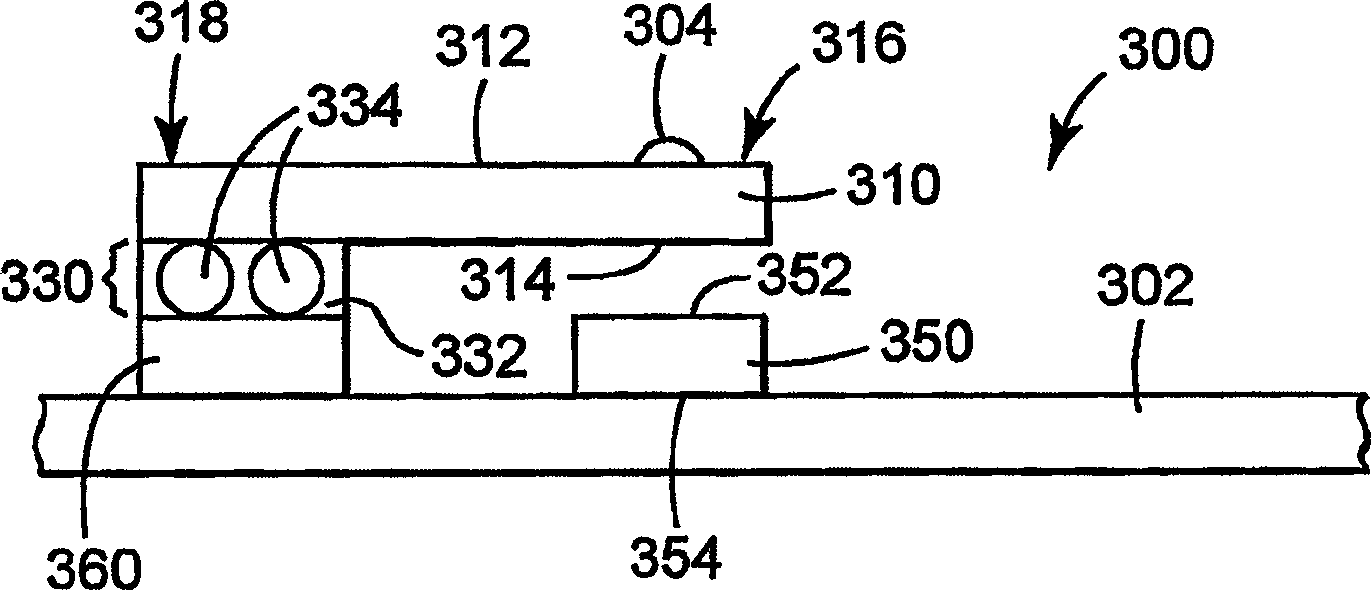
[0020] One aspect of the invention relates to a capacitive device configured to detect force differences over a continuous range of forces including zero force. The device includes a first electrod...


PUM

PropertyMeasurementUnit
thicknessaaaaaaaaaa
softening pointaaaaaaaaaa
Mohs hardnessaaaaaaaaaa

Abstract

The present invention provides a novel capacitive device configured to detect force differences over a continuous range of forces including zero force. The device includes a first electrode and a second electrode spaced apart from each other by a predetermined distance in a rest position. There is a measurable capacitance between the first electrode and the second electrode. A structural element having a predetermined maximum dimension is positioned in the device to control a predetermined distance between the first electrode and the second electrode. A force acting on the device causes a change in the distance between the first electrode and the second electrode and an associated change in capacitance which can be measured to determine information related to the force.

Description

technical field [0001] The present invention relates to force-based touch sensors, and more particularly to controlling the spacing between electrodes of force-based touch sensors. Background technique [0002] The ability to sense and measure contact forces and / or contact locations acting on a surface is useful in many different situations. Accordingly, various systems have been developed that use force sensors to measure a force (herein "contact force" or "action force") acting on a surface (herein "contact surface"). For example, a force sensor typically generates a signal corresponding to the applied force to determine the location of the applied force on the contact surface. [0003] Determining where the force is applied on the interface is of particular interest when the interface is that of a computer display or a clear coating on the front of a computer display. Furthermore, the rapid growth of mobile handheld devices such as Personal Digital Assistants (PDAs) has...

Claims


Application Information

Patent Timeline
Patent Type & Authority Applications(China)
IPC IPC(8): G01L1/14
CPCG01L1/142G01L1/146G01L1/14
Inventor 罗伯特·F·卡姆拉特迈克尔·E·豪迈尔利比利·L·韦弗
Owner 3M INNOVATIVE PROPERTIES CO
Why Eureka
Try Eureka