Device for drawing internal and outernal ring of bearing

A puller, inner and outer ring technology, applied in the field of machinery, can solve the problems that the disassembly device cannot be used normally, the bearing outer ring cannot be disassembled, and the working reliability is low, and achieves the effects of simple structure, low cost, and high use reliability.

Inactive Publication Date: 2006-06-28
张银根
View PDF1 Cites 4 Cited by
  • Summary
  • Abstract
  • Description
  • Claims
  • Application Information

AI Technical Summary

Problems solved by technology

However, the through hole 1 on the sleeve and the through hole 2 on the jacket must be larger than the through hole 1, and the processing requirements are cumbersome.
[0006] At the same time, the ball is easy to get stuck in the process of rotating the jacket, which causes the disassembly device to be unable to use normally, and its working reliability is not high
In addition, the dismounting device can only disassemble the inner ring of the bearing installed on the shaft, and cannot disassemble the outer ring of the bearing installed in the bearing seat

Method used


Image

  • Device for drawing internal and outernal ring of bearing
  • Device for drawing internal and outernal ring of bearing
  • Device for drawing internal and outernal ring of bearing

Examples


Embodiment 1

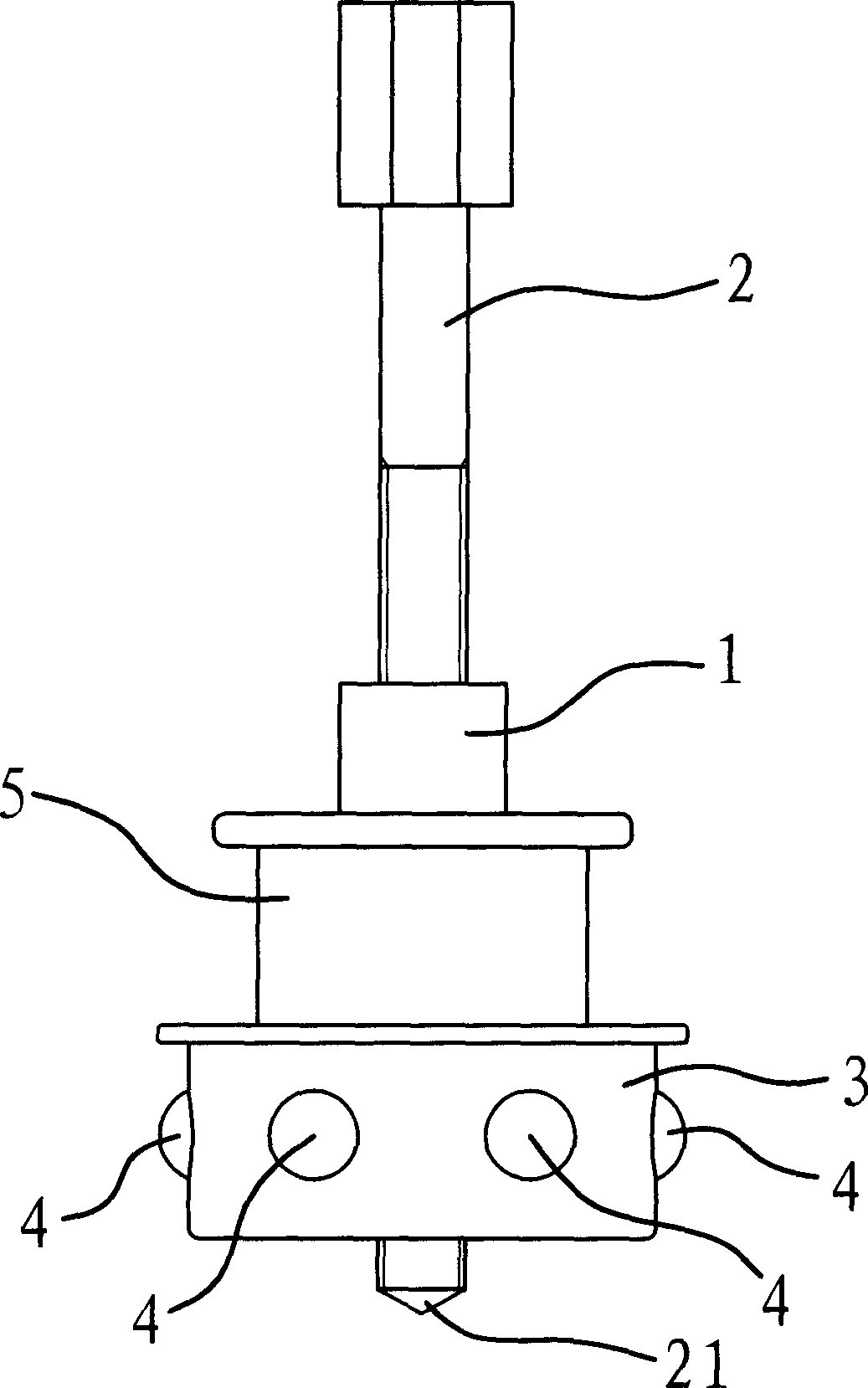
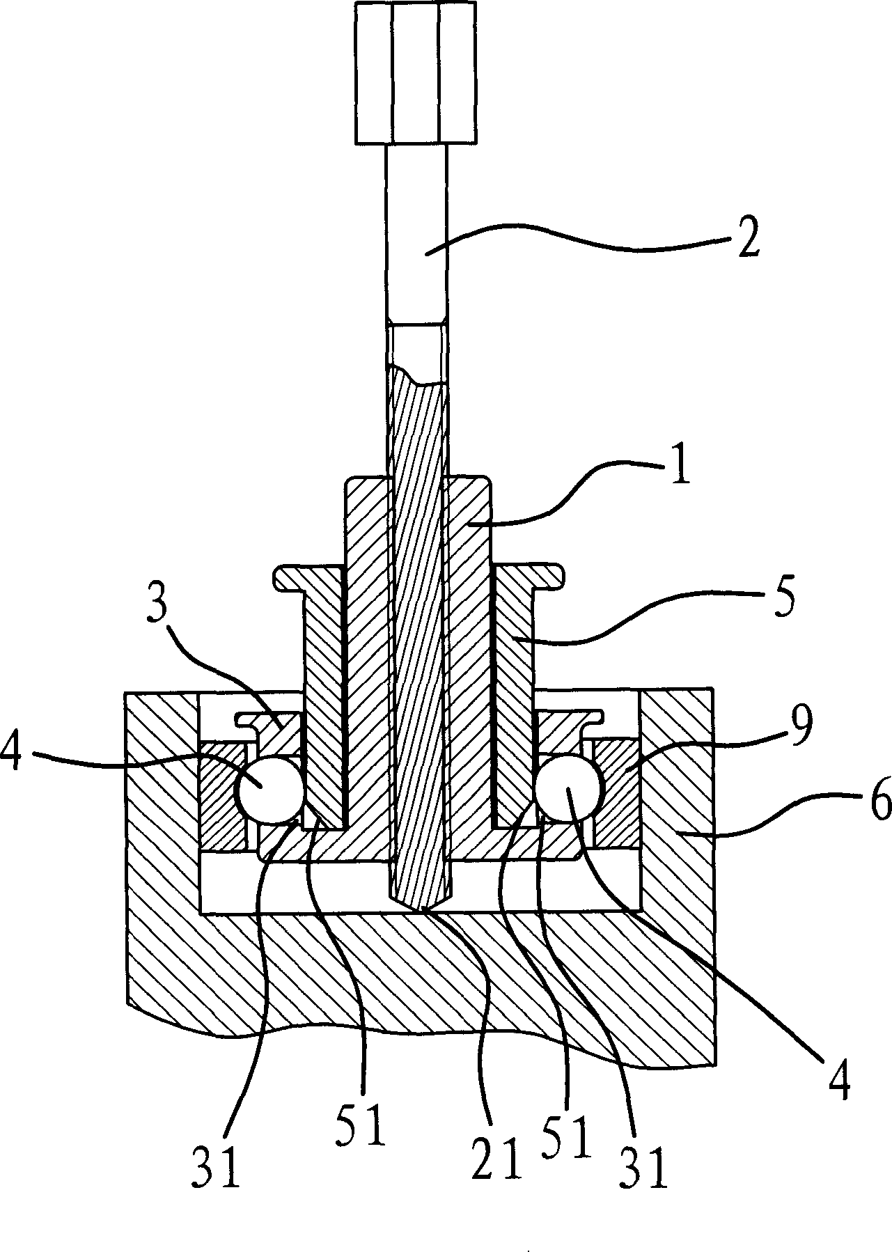
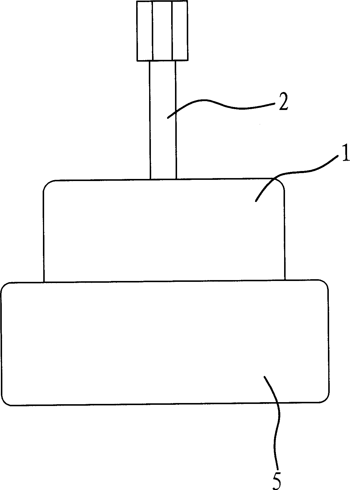
[0029] Such as figure 1 and figure 2 As shown, the bearing inner and outer ring puller is used to remove the bearing outer ring 9 installed in the bearing seat 6, and it includes a cylindrical main body 1, screw rod 2, slider seat 3, slider 4 and bushing 5 .

[0030] The middle part of the main body 1 is provided with a through threaded hole, and the screw rod 2 is connected in the threaded hole. The inner end of the screw rod 2 is a sharp angle 21, and the outer end is a regular hexagon. The operator can hold the regular hexagon at the outer end of the screw 2 to rotate the screw 2 .

[0031] The end of the main body 1 is fixedly connected with a slider seat 3, which is cylindrical. In this embodiment, for the convenience of processing, the main body 1 and the slider seat 3 adopt an integrated structure. The outer surface of the slider seat 3 is evenly provided with six through holes 31 , and each through hole 31 is equipped with a slider 4 . In this embodiment, the sli...

Embodiment 2

[0036]The principle and structure of this embodiment are basically the same as those of Embodiment 1, except that the diameter of the through hole 31 at the inner and outer surfaces of the slider seat 3 is slightly smaller than the outer diameter of the ball. The bushing 5 is directly sleeved on the outside of the slider seat 3 . In this embodiment, in order to prevent the bushing 5 from falling off, a stop edge 32 for blocking the bushing 5 is provided at the bottom of the slider seat 6 .

[0037] When in use, the slider seat 3 is sleeved on the bearing inner ring 8 . When the through hole 31 corresponds to the annular groove on the inner ring 8 of the bearing, put down the bushing 5 . The bushing 5 squeezes the slider 4 so that the slider 4 partially protrudes from the inner side of the through hole 31 , and the partially protruded slider 4 is stuck in the annular groove of the bearing inner ring 8 . At this time, turn the screw 2. When the sharp corner of the inner end of ...


PUM


Abstract

A pull-out device for internal and external rings of bearing is composed of a cylindrical main body, a screw bolt passing through said main body and coupled to main body via spiral threads, a cylindrical slide block seat fixed to the end of main body and with several through holes and an external diameter slightly less than the internal diameter of the external ring of bearing, several slide block in said through holes on slide block seat, and a lining sleeve of main body, whose end can be inserted in slide block seat to project slide blocks out of the slide block seat.

Description

technical field [0001] The invention belongs to the technical field of machinery, and relates to a manual disassembly tool, in particular to a puller used for disassembling the inner ring or outer ring of a bearing. Background technique [0002] At present, in the maintenance of machinery, especially in the maintenance of various vehicles and internal combustion engines, the situation of bearing damage is often encountered. Due to the interference fit between the bearing and the shaft or bearing seat, it is difficult to disassemble the bearing, and the disassembly effect is often not good. For example, after the inner ring of the bearing and the ball are removed, the outer ring of the bearing remains to be connected in the bearing seat, which causes great inconvenience to the maintenance work. [0003] In order to remove the remaining inner or outer ring of the shaft, the common method is to use oxygen cutting, and then take it out after cutting. Obviously, this is time-co...

Claims


Application Information

Patent Timeline
Patent Type & Authority Applications(China)
IPC IPC(8): B25B27/06
Inventor 张银根
Owner 张银根
Why Eureka
Try Eureka