
Winding test machine applicable to carbon fiber composite core rods

A composite mandrel and carbon fiber technology, which is applied in the direction of measuring devices, instruments, scientific instruments, etc., can solve the problems affecting the quality of the mandrel winding, dust falling on the mandrel, and time-consuming and laborious disassembly, so as to improve the winding effect and improve the Quality, the effect of improving the quality of winding

Active Publication Date: 2018-11-02
ANHUI CHUNHUI INSTR CABLE GROUP
View PDF18 Cites 3 Cited by
  • Summary
  • Abstract
  • Description
  • Claims
  • Application Information

AI Technical Summary

Problems solved by technology

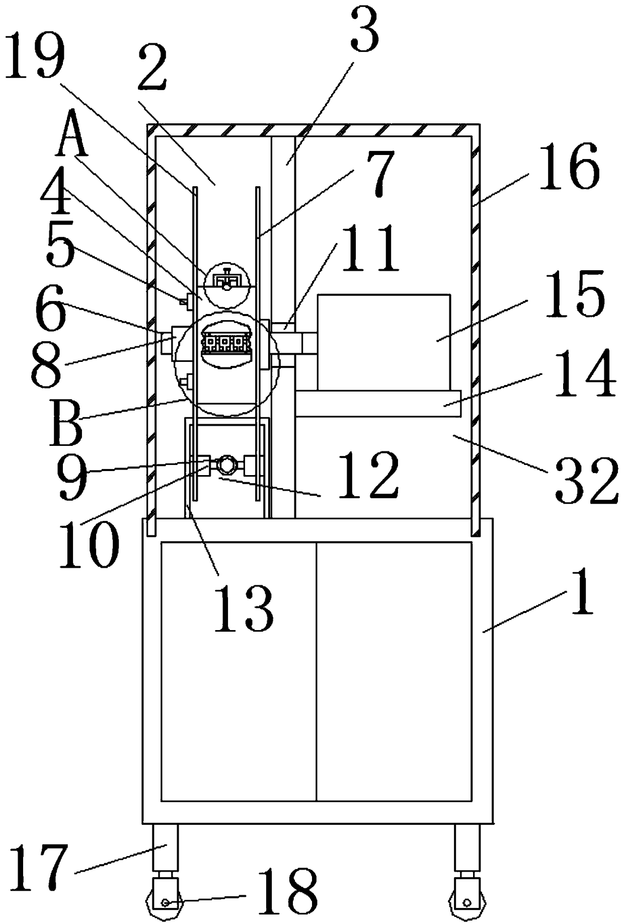
[0004] The purpose of the present invention is to solve the time-consuming and labor-intensive disassembly of the mandrel retracting mechanism in the prior art and the retracting mechanism is easy to cause the mandrel to fall off from the side of the reel. In addition, a lot of dust will fall on the surface of the mandrel during the winding process. The dust affects the quality of mandrel winding, and a winding test machine suitable for carbon fiber composite mandrel is proposed

Method used


Image

  • Winding test machine applicable to carbon fiber composite core rods
  • Winding test machine applicable to carbon fiber composite core rods
  • Winding test machine applicable to carbon fiber composite core rods

Examples


Embodiment Construction

[0024] The following will clearly and completely describe the technical solutions in the embodiments of the present invention with reference to the accompanying drawings in the embodiments of the present invention. Obviously, the described embodiments are only some, not all, embodiments of the present invention.

[0025] In describing the present invention, it should be understood that the terms "upper", "lower", "front", "rear", "left", "right", "top", "bottom", "inner", " The orientation or positional relationship indicated by "outside", etc. is based on the orientation or positional relationship shown in the drawings, and is only for the convenience of describing the present invention and simplifying the description, rather than indicating or implying that the referred device or element must have a specific orientation, so as to Specific orientation configurations and operations, therefore, are not to be construed as limitations on the invention.

[0026] refer to Figure ...


PUM


Abstract

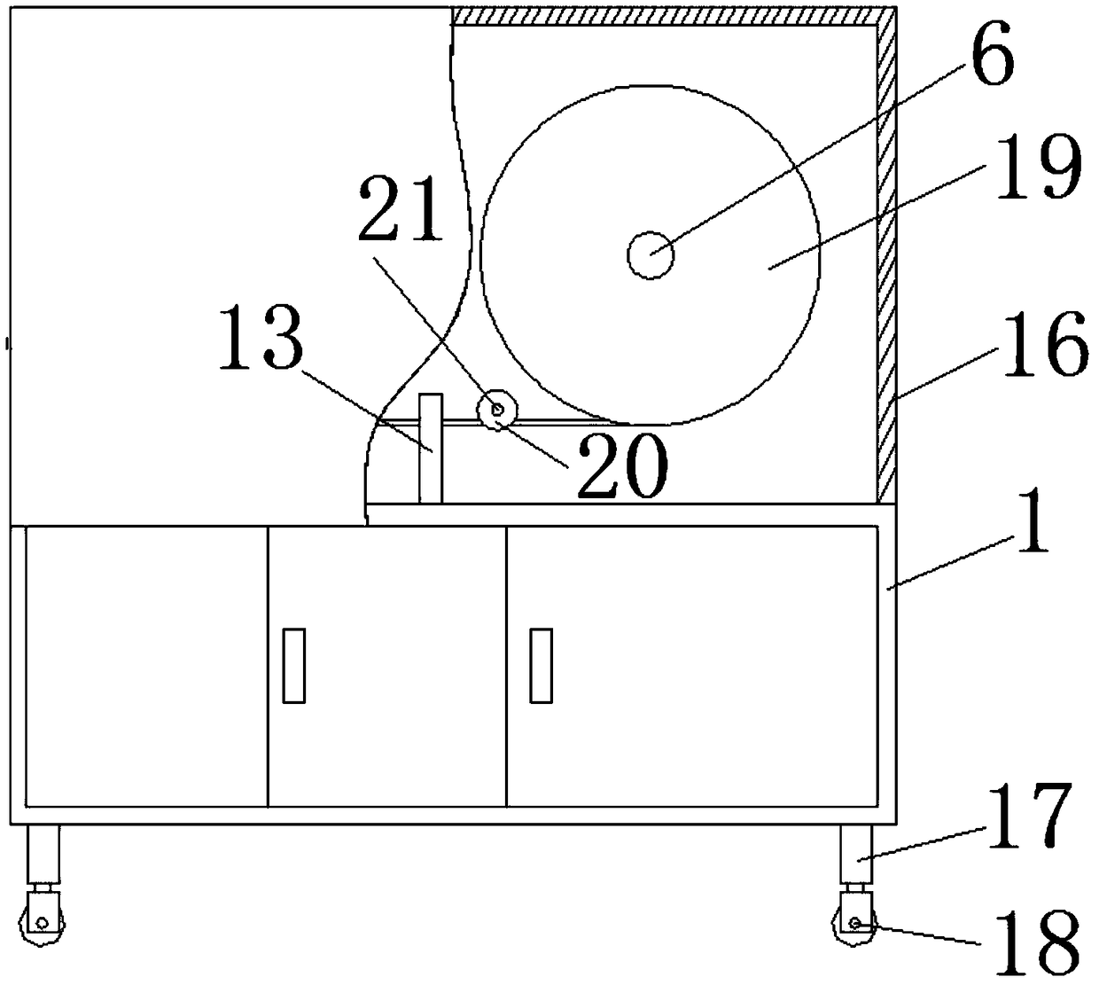
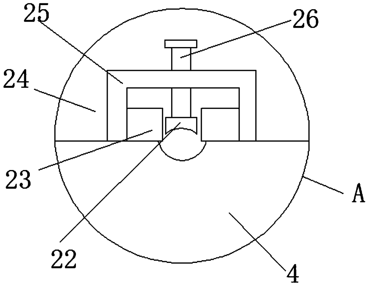
The invention discloses a winding test machine applicable to carbon fiber composite core rods. The winding test machine comprises a rack, wherein the upper surface of the rack is vertically and fixedly connected with a first supporting plate; a rolling bearing is fixedly arranged in the first supporting plate; the inner wall of the rolling bearing is fixedly connected with a threaded rod; a protective cover is movably connected to the upper surface of the rack; a deep groove matched with the bottom end of the protective cover is formed in the upper surface of the rack; the right side face of the first supporting plate is fixedly connected with a driving mechanism; the shaft wall of the threaded rod is sleeved with a winding mechanism in a sliding manner; and the upper surface of the rack is fixedly connected with a core rod surface cleaning mechanism. The winding test machine disclosed by the invention is convenient to operate, the first circular plate and the second circular plate canrealize core rod winding without dropping, and the core rod winding effect is improved. Moreover, the detachment process is time-saving and labor-saving, the core rod winding efficiency is improved,the core rod surface can be cleaned, and the core rod winding quality is improved.

Description

technical field [0001] The invention relates to the technical field of carbon fiber composite core rods, in particular to a winding test machine suitable for carbon fiber composite core rods. Background technique [0002] In recent years, a new type of wire - carbon fiber composite core wire has been widely used. The biggest difference between this new type of wire and ordinary steel-reinforced aluminum stranded wire is that the reinforcing core of the wire is a carbon fiber composite core (hereinafter referred to as the mandrel). The mandrel has the advantages of light weight, high strength and small linear expansion coefficient, which makes the wire have high strength, low line loss, small sag, high temperature resistance, large carrying capacity, light weight and corrosion resistance compared with traditional wires. Advantages, energy saving, environmental protection and safety of power transmission are realized, and the wire has a good application prospect in power trans...

Claims


Application Information

Patent Timeline
Patent Type & Authority Applications(China)
IPC IPC(8): G01N3/26G01N3/02
CPCG01N3/02G01N3/26G01N2203/028
Inventor 沈必亮王晓春
Owner ANHUI CHUNHUI INSTR CABLE GROUP
Learn More