Vehicle tire

A tire and vehicle technology, applied to vehicle parts, tire parts, tire tread/tread pattern, etc., can solve the problem that it is difficult to predict the maximum sound level of noise

Inactive Publication Date: 2010-05-05
SUMITOMO RUBBER IND LTD
View PDF8 Cites 0 Cited by
  • Summary
  • Abstract
  • Description
  • Claims
  • Application Information

AI Technical Summary

Problems solved by technology

Furthermore, even if the axial grooves are sloped, it is difficult to predict when the noise of an axial groove will reach its maximum sound level
Like this, it is difficult to determine whether said synchronization occurs by comparing specific positions (such as ends) of the grooves.

Method used


Image

  • Vehicle tire
  • Vehicle tire
  • Vehicle tire

Examples


Embodiment Construction

[0018] In the present embodiment, the vehicle tire 1 according to the present invention is a pneumatic radial tire for passenger cars. As is well known to those skilled in the art, a pneumatic tire includes a tread portion, a pair of axially spaced bead portions, and a pair of sidewall portions extending between the tread edge and the bead portion.

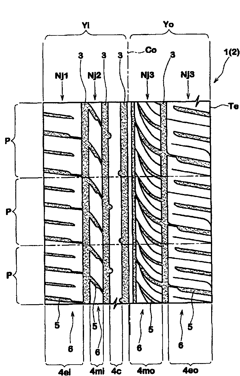
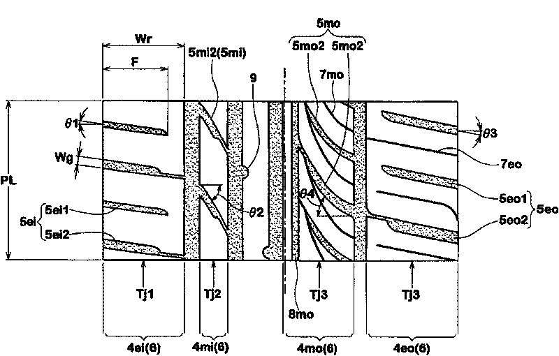
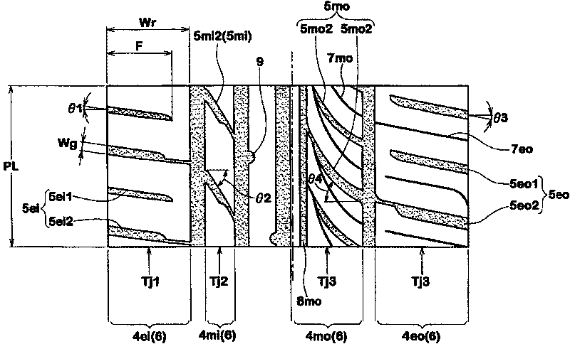
[0019] Said tread portion 2 is provided with tread grooves and optional sipes defining the tread pattern. figure 1 An example of a tread pattern is shown, which is suitable for a minivan and is designed to provide low noise and handling stability.

[0020] The tread groove comprises a plurality of main grooves 3 extending continuously in the circumferential direction of the tire, thereby axially dividing the tread portion 2 into at least three annular regions 4 .

[0021] Here, the main groove 3 in the circumferential direction is a groove with a width of not less than 2.0 mm, which is provided for drainage. Therefore, narrow gr...


PUM


Abstract

A pneumatic tire comprises a tread portion provided with annular regions each provided with axial grooves each extending from one of the axial edges of the annular region, wherein each axial groove isdefined as having a groove width of from 2.0 to 6.0 mm and an axial length of not less than 40% of the axial width of the annular region. The annular regions are different from each other with respect to the number Nj of the axial grooves therein, and the greatest common divisor of the different numbers Nj of the grooved annular regions is in a range of from 10 to 40.

Description

technical field [0001] The present invention relates to a vehicle tire, and more particularly, to a tread pattern capable of improving noise performance. Background technique [0002] Vehicle noise is mainly a combination of tire noise and mechanical noise generated by the engine, transmission, etc. [0003] Mechanical noise has been significantly reduced in recent years. In particular, in the case of hybrid cars and battery cars, when electric motors are used, the mechanical noise is almost zero. Under such circumstances, there is an urgent need for tire manufacturers to produce tires that generate less noise. [0004] Hitherto, as is well known to those skilled in the art of tread design, the so-called variable pitch method has almost always been used as an effective way of reducing tire noise. In the variable pitch method, the periodicity of the circumferential repetition of the tread elements is reduced so that no significant peaks in the noise spectrum, or elevated s...

Claims


Application Information

Patent Timeline
Patent Type & Authority Patents(China)
IPC IPC(8): B60C11/117
CPCB60C2011/0383B60C2011/0388B60C11/0318B60C11/033B60C11/0304B60C2011/0381
Inventor 白水利通
Owner SUMITOMO RUBBER IND LTD
Why Eureka
Try Eureka