
Combined insertion piece

A combined and inserting technology, which is applied in the direction of textiles and papermaking, weft knitting, knitting, etc., can solve the problems of easy formation of missing stitches, easy shaking, and influence on accuracy, so as to improve weaving quality, strengthen stability, and improve The effect of stability

Inactive Publication Date: 2006-06-28
冯加林
View PDF0 Cites 3 Cited by
  • Summary
  • Abstract
  • Description
  • Claims
  • Application Information

AI Technical Summary

Problems solved by technology

However, the structure of the existing insert makes it impossible to move the position of the plug iron groove 13 forward or to widen the groove width, so it is difficult to improve the stability of the knitting needle movement on the original basis, which is very important for improving the knitting quality. Unfavorable, especially when the knitting needle is used for transfer, the knitting needle needs to move smoothly and the needle should be ejected accurately
This is because: the knitting needle 4 on the high needle side has a high needle exit position, and the contact length C between its rear part and the plug iron becomes shorter, and the groove width L length without the plug iron groove 13 is S<L, and its front part stretches The length becomes longer, the stability of the knitting needle 4 is poor, and it is easy to shake. The accuracy of inserting the knitting needle 4' on the low needle side into the corresponding stitch on the high needle position is affected, and it is easy to form missing stitches.

Method used


Image

  • Combined insertion piece
  • Combined insertion piece
  • Combined insertion piece

Examples


Embodiment Construction

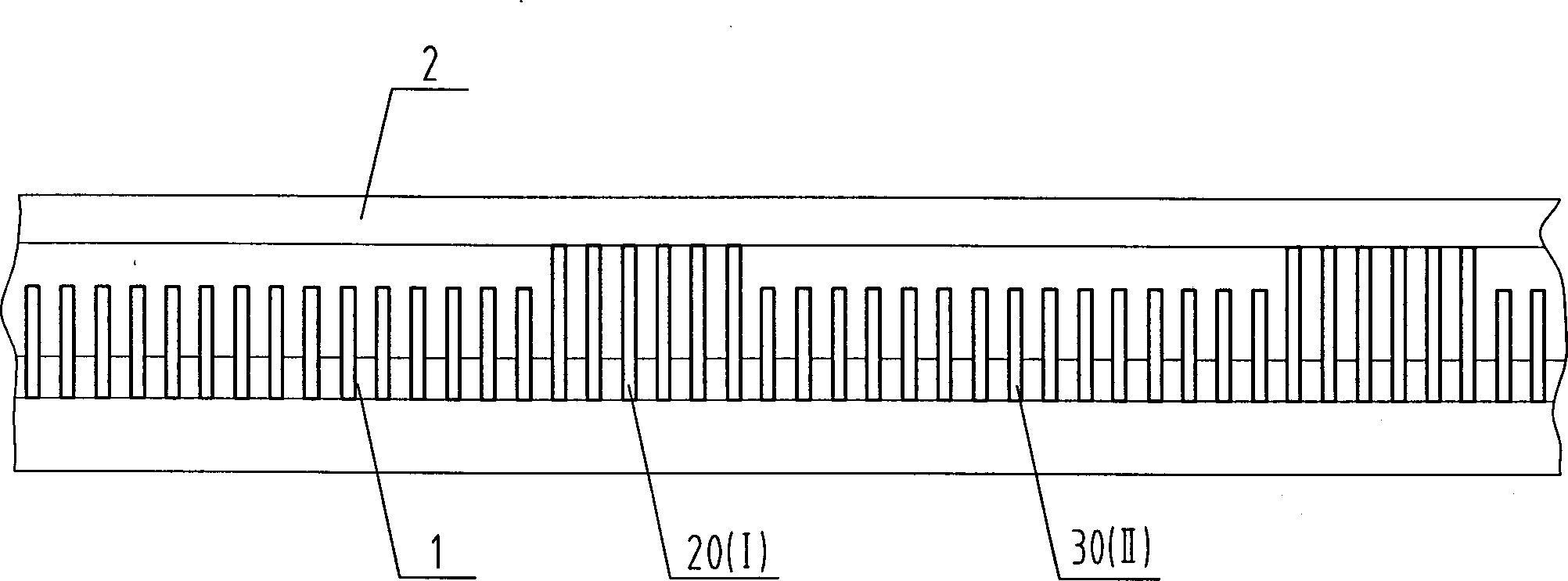
[0018] control image 3 , Insert I and the existing ( figure 1 ) of the inserting piece does not have a protruding head compared, and the head is straight, and is provided with a plug iron groove 13 on it. control Figure 4 , Inserting sheet II has similar protruding head 11 compared with existing inserting sheet, but is a plugging iron hole 31 on the iron slot position of the underside of protruding head 11. In this embodiment, the insertion piece I and the insertion piece II are made of 65Mn steel material with a thickness of 1 mm. Wherein insert piece 1 head front end is implemented by the following three schemes from the spacing S of the front end of 13 groove bottoms of plug iron groove on it: S=1 millimeter; S=2 millimeter; is 15mm.

[0019] control Figure 5 , every 5 inserts I are adjacently arranged and inserted in the insert slots on the needle plate to form an insert group I, and every 15 inserts II are adjacently arranged and inserted in the insert slots on th...


PUM


Abstract

The invention relates a to combined type filling-in bits. Its technical proposal is as follows: it is filled in filling-in bit groove; plug iron is filled in plug iron groove; it includes filling-in bit I and II; many of them are respectively filling-in bit set I and II; they are alternately arranged at clothing sheet; the head of the filling-in bit I is straight and set plug iron groove; the head of the filling-in bit II is set clothing sheet splicing groove; its lower side is set plug iron hole; the plug iron is set in it. Its advantages are that the place of the plug iron can be moved forwardly to the allowed place; the firmness of front end of knitting needle is obviously improved; the stability of braiding action is increased to improve braiding quality.

Description

technical field [0001] The invention relates to a knitting machine, in particular to a combined insert on a needle plate. Background technique [0002] The inserts are inserted into a number of insert slots arranged in parallel on the needle plate of the flat knitting machine, and the needle plate is divided into several needle slots for placing knitting needles and related needle butts and inserting and installing related zeros on the needle plate. part. The structure of the existing insert is as follows figure 1 As shown, there is a protruding head 11 at the front end of the insertion piece 10, on which a sinker needle plate insertion groove 12 is provided, and a plug iron groove 13 is provided on the inner side of the protruding head 11. Sinker needle plate insertion slot 12 is used to install sinker needle plate 2, plug iron slot 13 is used to insert plug iron 3, please refer to figure 2 . The plug iron 3 is on the upper side of the needle groove where the knitting ...

Claims


Application Information

Patent Timeline
Patent Type & Authority Applications(China)
IPC IPC(8): D04B15/00
Inventor 冯加林巫友群
Owner 冯加林
Learn More