Method and apparatus for eye alignment

An eye and eye tracking technology, applied in the field of refractive surgery, can solve problems such as eccentric ablation and error

Inactive Publication Date: 2006-06-28
BAUSCH & LOMB INC
View PDF0 Cites 12 Cited by
  • Summary
  • Abstract
  • Description
  • Claims
  • Application Information

AI Technical Summary

Problems solved by technology

This subjective technique is prone to error, which can lead to off-center ablation and other deficiencies in satisfying vision correction

Method used


Image

  • Method and apparatus for eye alignment
  • Method and apparatus for eye alignment
  • Method and apparatus for eye alignment

Examples


Embodiment Construction

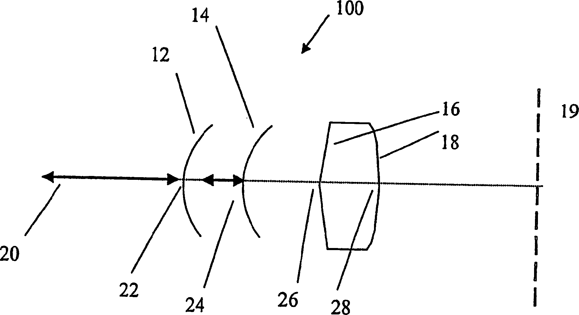
[0014] The present invention relates to an apparatus and method for objectively aligning the optical axis of a patient's eye with the diagnostic or therapeutic portion of a refractive vision correction surgical system, such as the beam axis of an excimer laser. An embodiment of the invention also relates to automatic engagement or triggering of eye trackers in such a system. The invention is based on detecting the co-alignment of the first and second Purkinje reflexes of the patient's eye, as figure 1 shown. exist figure 1 , a cross-section of an eye 100 is schematically shown, including an anterior corneal surface 12, a posterior corneal surface 14, an anterior lens surface 16, a posterior lens surface 18, and a retinal surface 19 (shown in straight dashed lines for illustrative purposes). Those of ordinary skill in the art have long recognized that when the input beam 20 properly strikes the eye, four Purkinje reflections can be detected. The first Purkinje reflection 22 ...


PUM


Abstract

In an ocular laser system, preferably for photoablative refractive surgery, a component device, preferably an optical coherence tomography device, for measuring corneal thickness detects the first and second Purkinje reflection is used for its measurement, otherwise, the reflected signal is not strong enough for OCT measurement. The beam axis of the system therapeutic laser is aligned with the OCT probe beam. When the first and second Purkinje reflections of the OCT probe beam are detected, the OCT device generates a signal and sends the signal to the eye tracker part of the system, starting the eye tracker. This objectively enables automatic engagement of the eye tracker and alignment of the patient optical axis with the treatment axis or diagnostic beam axis.

Description

technical field [0001] The present invention relates generally to the field of refractive surgery, and more particularly to systems, devices and methods for aligning an eye and engaging an eye tracker. Background technique [0002] Whenever a surgical procedure is performed, extreme accuracy is usually required. This need is important when performing surgery on a part of the body with involuntary movements. In the preferred field of the instant invention, refractive surgery is performed on the patient's eye following normal procedures, such as known as LASIK, or similar procedures such as PRK or LASEK. In these cases, a laser beam with a wavelength of 193 nm is usually used to photoablate part of the volume of the exposed corneal surface, forming a new shape of the corneal surface, thereby correcting the visual defect. [0003] Generally, aligning the patient's eyes is a problem. The eyes make rapid blinks, which are small quick involuntary movements. One may intentional...

Claims


Application Information

Patent Timeline
Patent Type & Authority Applications(China)
IPC IPC(8): A61B3/113A61F9/008A61F9/01
CPCA61B3/113A61F9/008A61F2009/00846A61F2009/00872G01B9/02091
Inventor 格哈德·优素菲弗里德里希·莫里茨
Owner BAUSCH & LOMB INC
Why Eureka
Try Eureka