Subassembly of imaging displacement and optical projection device
A technology of imaging position and displacement, applied in the direction of using projection device image reproducer, optics, projection device, etc., to achieve the effect of improving horizontal definition and vertical definition, and improving column definition
- Summary
- Abstract
- Description
- Claims
- Application Information
AI Technical Summary
Problems solved by technology
Method used
Image

Examples
Embodiment Construction
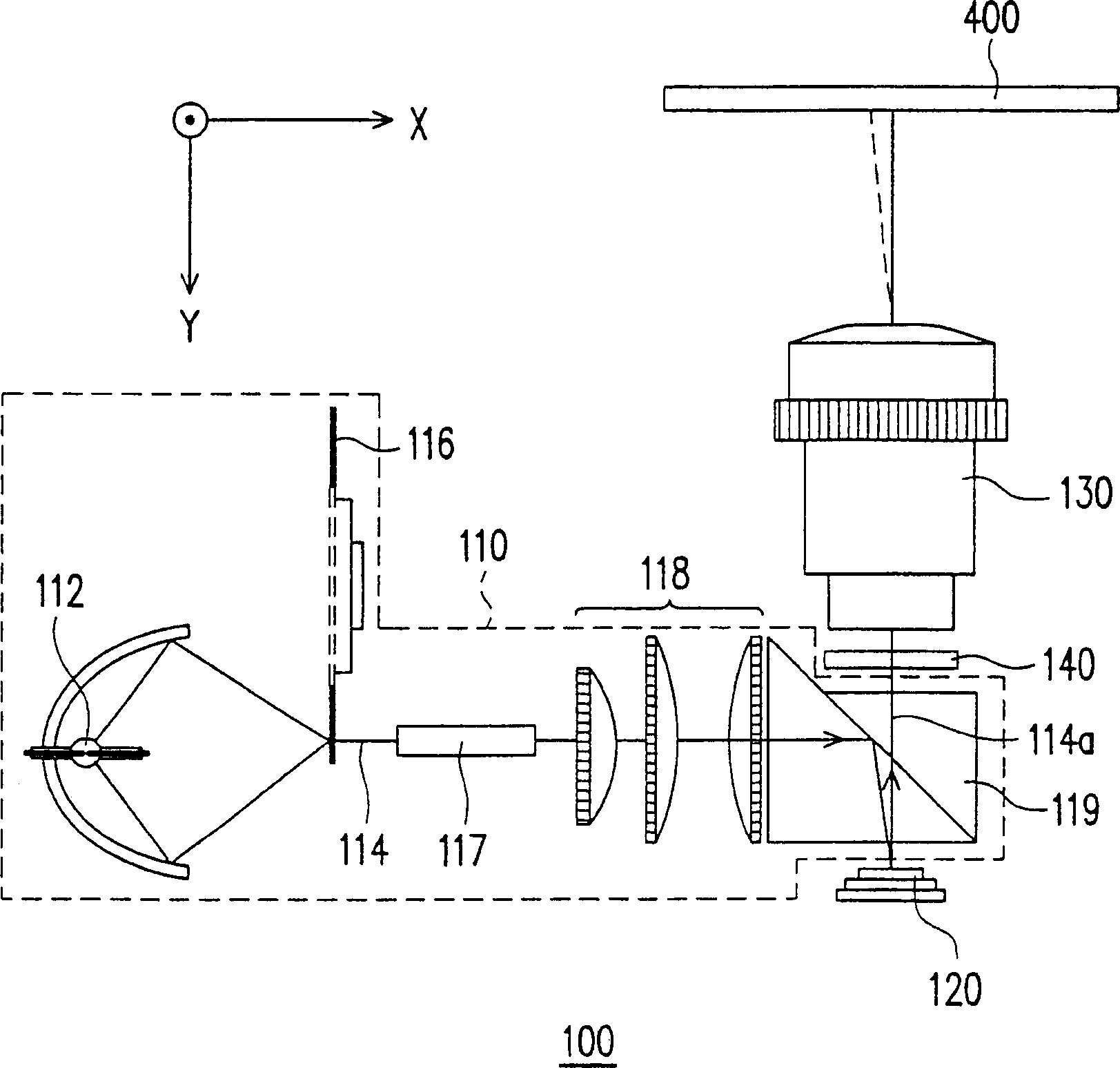
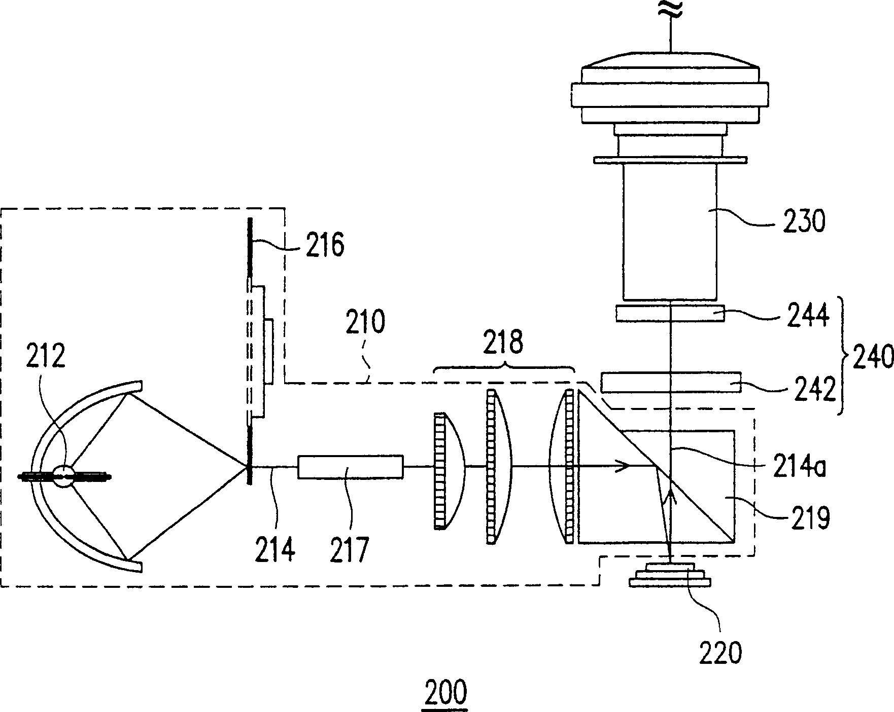
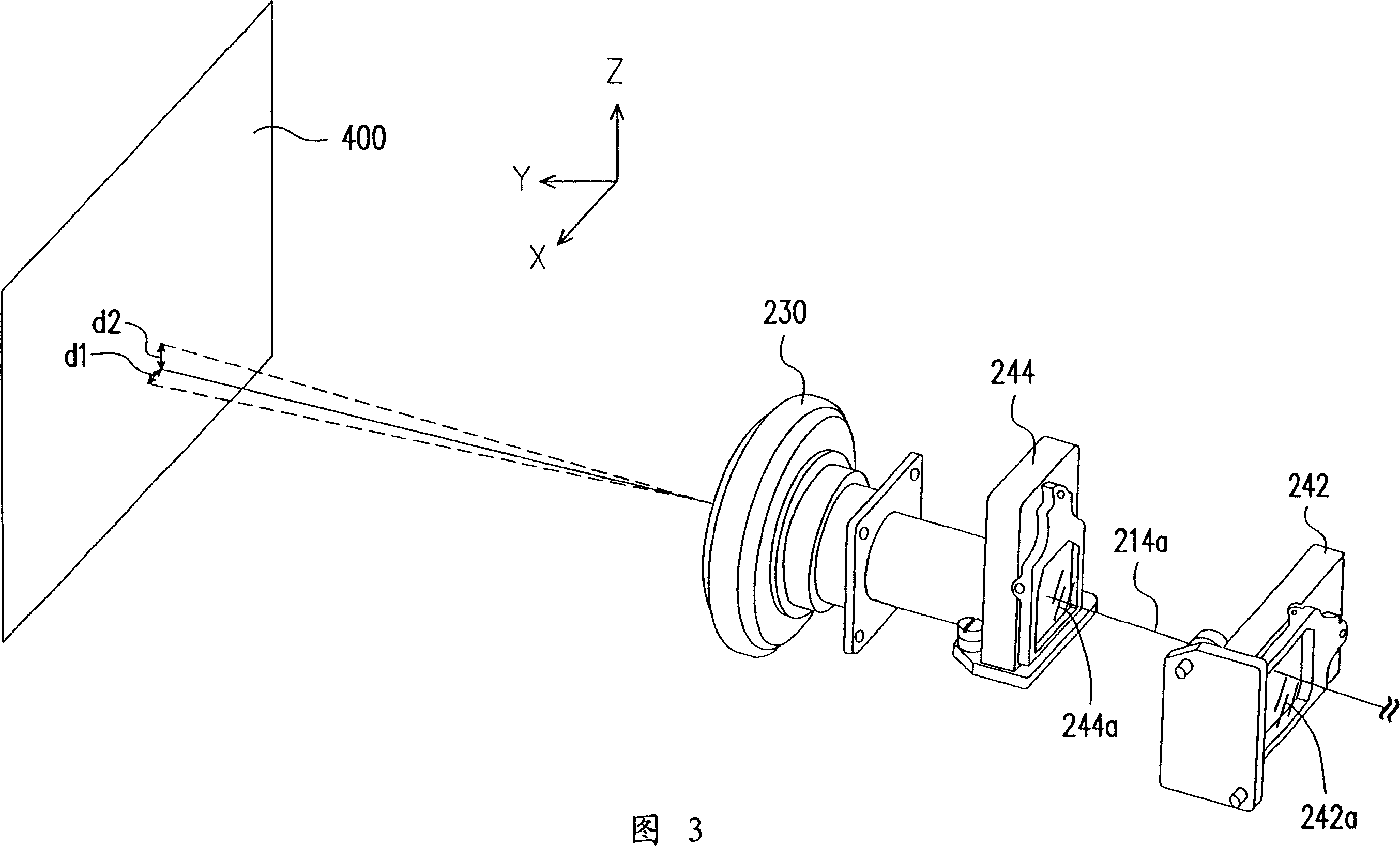
[0068] figure 2 is a schematic structural view showing an optical projection device according to a preferred embodiment of the present invention, and FIG. 3 is a perspective view showing a projection lens and an imaging displacement assembly. refer to figure 2 Similar to FIG. 3 , the optical projection device 200 of this embodiment includes an illumination system 210 , a reflective light valve 220 , a projection lens 230 and an image displacement assembly 240 . Wherein, the lighting system 210 has a light source 212 suitable for providing a light beam 214 , and the reflective light valve 220 is arranged on the transmission path of the light beam 214 . The reflective light valve 220 is adapted to convert the light beam 214 into a plurality of sub-images 214a within each frame time. In addition, the projection lens 230 is disposed on the transmission path of the sub-images 214a, and the reflective light valve 220 is located between the illumination system 210 and the project...
PUM
 Abstract
Description
Claims
Application Information
 - R&D
- Intellectual Property
- Life Sciences
- Materials
- Tech Scout
- Unparalleled Data Quality
- Higher Quality Content
- 60% Fewer Hallucinations
Browse by: Latest US Patents, China's latest patents, Technical Efficacy Thesaurus, Application Domain, Technology Topic, Popular Technical Reports.
© 2025 PatSnap. All rights reserved.Legal|Privacy policy|Modern Slavery Act Transparency Statement|Sitemap|About US| Contact US: help@patsnap.com