Center post of annular field coil in global Tokamak magnet

A tokamak and central column technology, applied in the direction of plasma, greenhouse gas reduction, nuclear reactor, etc., can solve the problems of adding cooling system, complex process, low conductor filling rate, etc., to increase the conductive area, improve safety, The effect of reducing thermal stress

Inactive Publication Date: 2006-07-05
INST OF ELECTRICAL ENG CHINESE ACAD OF SCI
View PDF1 Cites 12 Cited by
  • Summary
  • Abstract
  • Description
  • Claims
  • Application Information

AI Technical Summary

Problems solved by technology

[0004] In order to overcome the disadvantages of low conductor filling rate, complicated process, and the need to add an additional cooling system due to the forced water cooling structure of the center column in the prior art, the present invention proposes a spherical tokamak toroidal field magnet coil with a new structure. Turn current collection center column

Method used


Image

  • Center post of annular field coil in global Tokamak magnet
  • Center post of annular field coil in global Tokamak magnet
  • Center post of annular field coil in global Tokamak magnet

Examples


Embodiment Construction

[0017] The present invention will be further described below in conjunction with the accompanying drawings and specific embodiments.

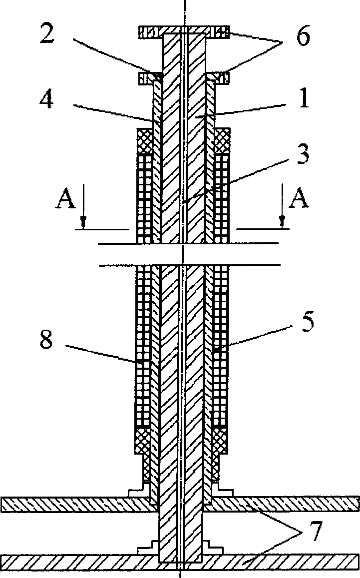
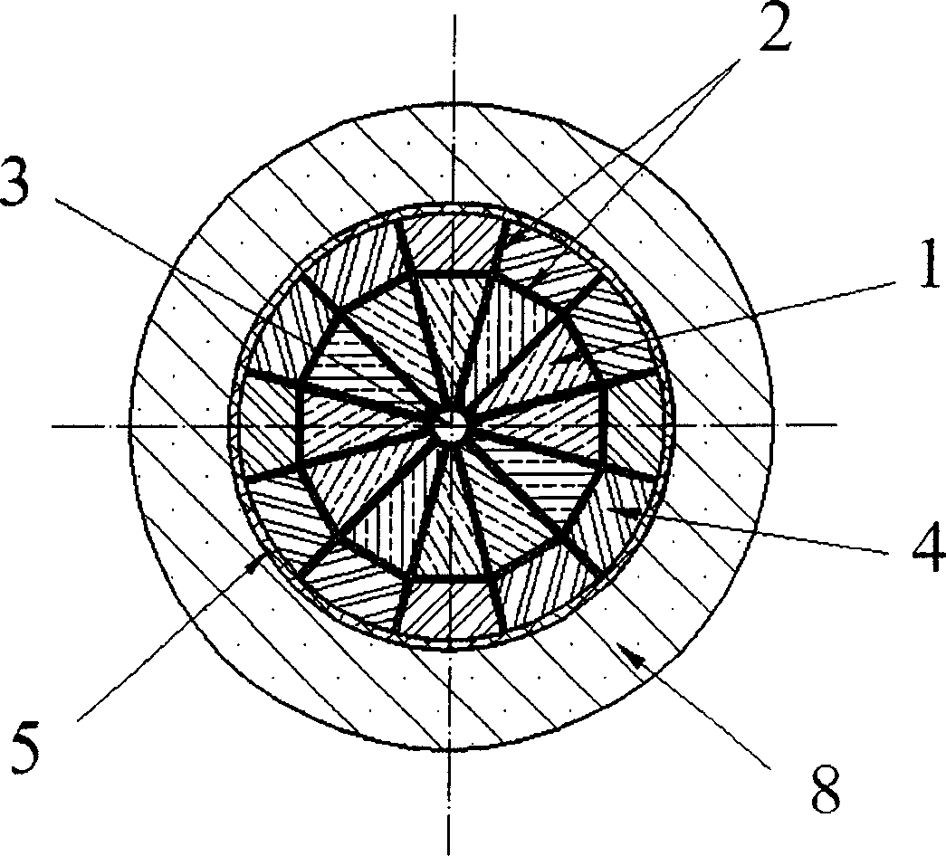
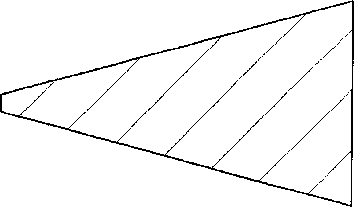
[0018] figure 1 It is a structural diagram of the present invention, in which the central column of the present invention is composed of inner and outer layers of special-shaped conductors, and each of the inner and outer layers of special-shaped conductors has 12 pieces, which are evenly distributed and arranged along the circumferential direction. The upper and lower ends of each shaped conductor are welded with connecting terminals 6 and 7 distributed along the circumference and perpendicular to the axis of the central column. The inner conductor 1 of the central column is made of oxygen-free copper material through extrusion molding; the epoxy glass laminate 2 has a thickness of 1 mm; the central cooling hole 3 is automatically formed when the inner conductor 1 is arranged along the circumferential direction; the central column The outer c...


PUM


Abstract

The invention is a central column for a spherical tokamak magnet toroidal field coil, composed of inner and outer profile conductor layers, where all profile conductors are circumferentially and uniformly distributed; sections of 12 profile conductors are trapeziform in shape, and short bases of them are circularly arranged opposite to the center of the central column; centers of them are formed with natural air flow cooling holes; sections of 12 outer profile conductors are of a quasi-trapezoid with an long arc side in shape, the arc bases of them are opposite to outer surface of the central column and circularly arranged outside the inner profile conductors to form the outer layer of the central column. The top-end and bottom-end terminals of each profile conductor are connected with a turning arm to form a turn of the toroidal field coil, thus forming 24 turns in common; there is a current flowing through each profile conductor and these currents are codirectional and equal, corresponding to ampere-turn of the toroidal field coil. The invention can permit the maximum 12000A pulse current to flow through the toroidal field coil but the inner temperature does not obviously rise.

Description

technical field [0001] The invention relates to the structure of a spherical tokamak toroidal field magnet, in particular to the center column of each turn current of the tokamak toroidal field magnet coil. Background technique [0002] The biggest difference between the spherical tokamak device and the traditional fusion tokamak device is that it has a smaller ring diameter ratio. A small ring diameter ratio will mean that the utilization efficiency of the toroidal field is higher, so the magnetic field requirements for the toroidal field can be lower. For example, the hoop field of a spherical tokamak is about an order of magnitude lower than that of a traditional tokamak. The scale of the spherical tokamak device is much smaller than that of the traditional tokamak device, and the engineering cost is much lower. [0003] In order to obtain the low ring-to-diameter ratio of the spherical tokamak, the structure of the toroidal field magnet is required to be very compact, ...

Claims


Application Information

Patent Timeline
Patent Type & Authority Applications(China)
IPC IPC(8): G21B1/00H05H1/02
CPCY02E30/122Y02E30/10
Inventor 戴银明余运佳南和礼
Owner INST OF ELECTRICAL ENG CHINESE ACAD OF SCI
Why Eureka
Try Eureka