Liquid jet polishing method

A liquid and polishing liquid technology, applied in spray guns, explosion generating devices, abrasives, etc., can solve problems such as difficult to achieve numerical control operation

Inactive Publication Date: 2006-07-19
SUZHOU UNIV
View PDF0 Cites 6 Cited by
  • Summary
  • Abstract
  • Description
  • Claims
  • Application Information

AI Technical Summary

Problems solved by technology

It can be seen that with these commonly used injection methods, the removal function obtained is very different from the ideal removal function, so it is difficult to realize the numerical control operation

Method used


Image

  • Liquid jet polishing method
  • Liquid jet polishing method
  • Liquid jet polishing method

Examples


Embodiment 1

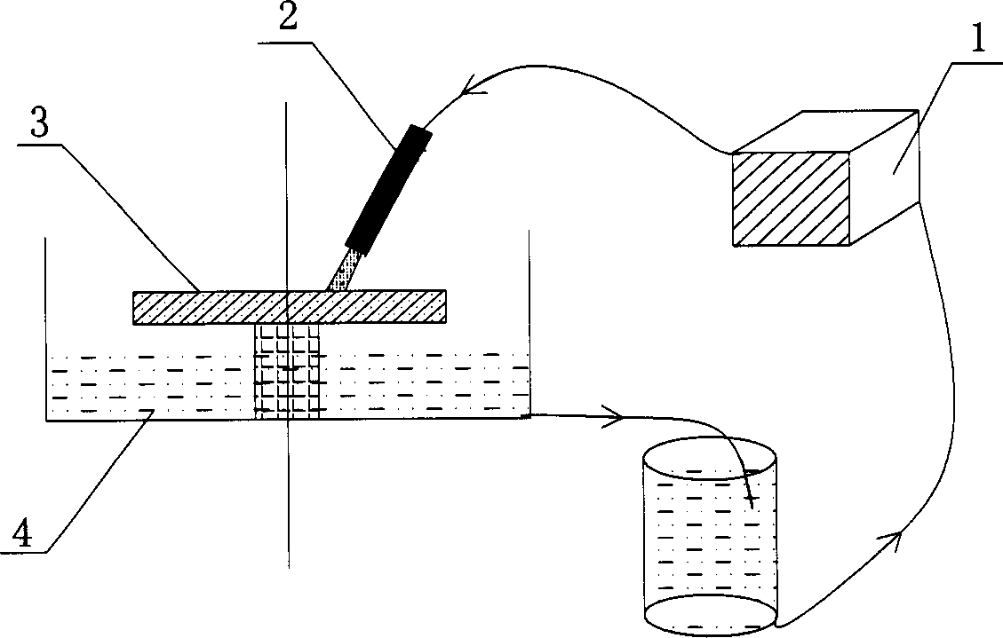
[0027] Embodiment one: see attached image 3 and 4 As shown, a method of liquid jet polishing, the polishing liquid mixed with abrasive particles is accelerated by a high-pressure pump, ejected from the nozzle, shot at the surface of the workpiece, collides with the workpiece, and polishes the surface of the workpiece. The diameter of the tube is 1.2 mm. The workpiece rotates around the normal line of the center of the processing area. The axis of the nozzle tube is perpendicular to the tangent plane of the center of the processing area. The distance between the intersection point of the extension line of the tube axis and the surface of the workpiece and the center of the processing area is about 1 mm. , the workpiece is rotated at an angular velocity ω=168 rpm, the working distance is 7 mm, the working pressure is 4.5 bar, the action time is 8 minutes, and the polishing liquid is sprayed continuously.

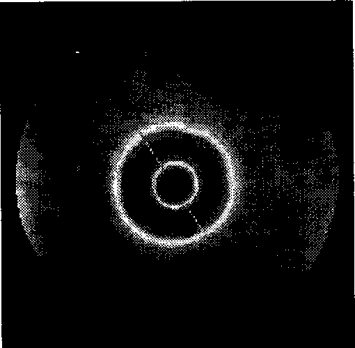
[0028] See attached image 3 Shown is a schematic diagram of the distr...

Embodiment 2

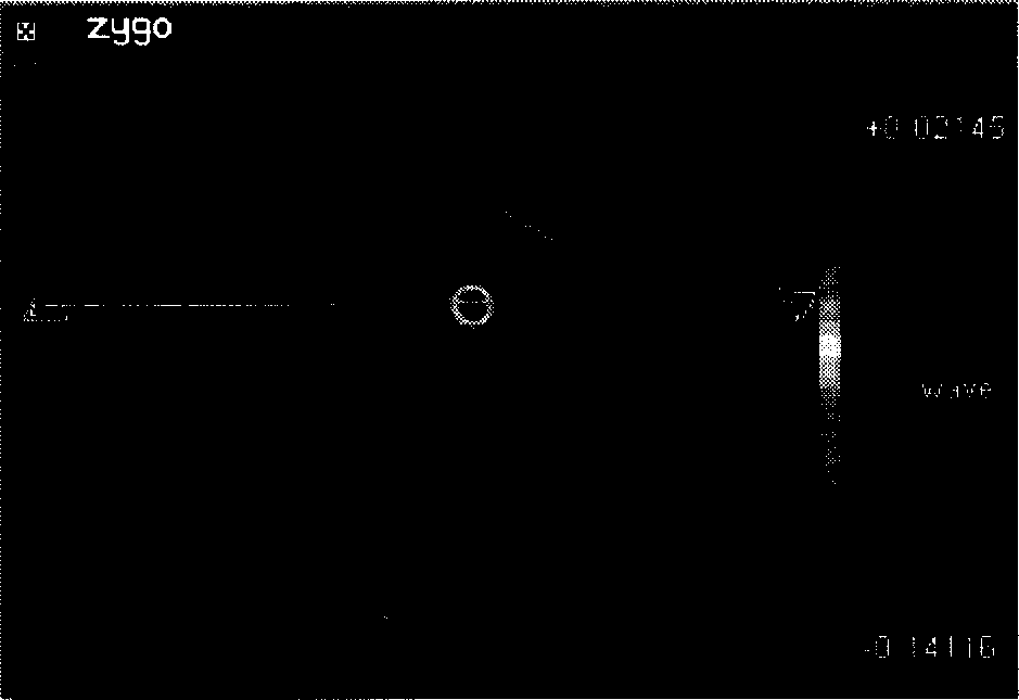
[0029] Embodiment two: see attached Figure 5 As shown, a method of liquid jet polishing, the polishing liquid mixed with abrasive particles is accelerated by a high-pressure pump, ejected from the nozzle, shot at the surface of the workpiece, collides with the workpiece, and polishes the surface of the workpiece. The axis of the tube is perpendicular to the cut surface of the center of the processing area, the polishing liquid is sprayed in gaps, the nozzle rotates one circle relative to the center of the processing area, and the polishing liquid is sprayed 4 times.

Embodiment 3

[0030] Embodiment 3: A method for liquid jet polishing. The polishing liquid mixed with abrasive particles is accelerated by a high-pressure pump, ejected from the nozzle, and shot at the surface of the workpiece, colliding with the workpiece, and polishing the surface of the workpiece. The angle between the pipe axis of the nozzle and the tangent plane at the center of the processing area is 60°, and the polishing liquid is sprayed continuously.


PUM


Abstract

The invention discloses a liquid injection polishing method, which is characterized by the following: accelerating the abrading particle through high-pressure pump; spraying the abrading particle through nozzle on the workpiece surface to generate collision; polishing the workpiece surface; adapting the normal line of manufacturing domain center as axle to make nozzle and workpiece rotate relatively; letting the separation angle of nozzle pipe axle and tangent plane of manufacturing region center range from 30 to 90 deg and d as nozzle internal diameter. When the separation angle is 90 deg, the distance between intersection point of pipe axial elongation line and workpiece surface and manufacturing region center is from 0.5d to 1d; when the separation angle is less than 90 deg, the distance between intersection point of pipe axial elongation line and workpiece surface and manufacturing region center is from 0.2d to 1d. The invention can obtain ideal removal function to realize digital control polish, which is fit for optical manufacturing.

Description

technical field [0001] The invention relates to an optical polishing process, in particular to a liquid jet polishing method, which is especially suitable for the polishing treatment of optical elements. Background technique [0002] Liquid jet polishing technology is a new optical polishing process, which relies on the high-speed flowing liquid and the abrasive particles carried by it to scour the surface of the workpiece to achieve the purpose of polishing. Compared with the traditional polishing technology, the advantage of liquid jet polishing is that the processing tool is liquid, there is no wear of the polishing disc, the removal function remains constant, and the surface accuracy is easy to control; at the same time, because the polishing liquid is constantly Circulating flow can keep the temperature of the polished workpiece constant, and can also automatically remove the processed debris; moreover, the polishing head is realized by a small...

Claims


Application Information

Patent Timeline
Patent Type & Authority Applications(China)
IPC IPC(8): B24C1/08B24C5/04
Inventor 郭培基方慧
Owner SUZHOU UNIV
Why Eureka
Try Eureka