Method for polishing computer-controlled gadget

A computer and small tool technology, applied in the direction of manufacturing tools, surface polishing machine tools, grinding/polishing equipment, etc., can solve the problems that affect the quality of the surface shape, do not have the ability to remove materials, etc., and achieve the effect of eliminating high-frequency errors

Inactive Publication Date: 2012-09-05
SUZHOU UNIV
View PDF0 Cites 0 Cited by
  • Summary
  • Abstract
  • Description
  • Claims
  • Application Information

AI Technical Summary

Problems solved by technology

(3) Outside the maximum radius of the removal function, it does not have the ability to remove material
However, the removal functions produced by these two motion methods are far from the ideal removal function, and the medium and high frequency errors generated in the later stage of processing seriously affect the quality of the surface shape.

Method used


Image

  • Method for polishing computer-controlled gadget
  • Method for polishing computer-controlled gadget
  • Method for polishing computer-controlled gadget

Examples


Embodiment 1

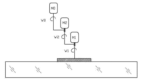
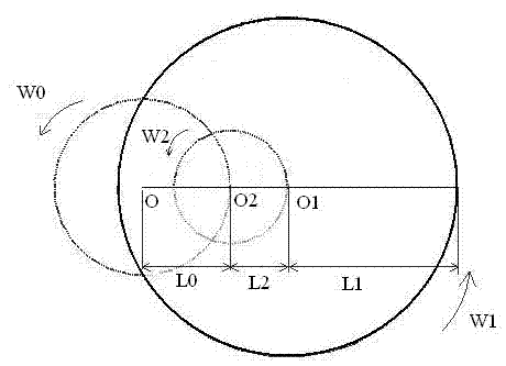
[0022] Embodiment one: see attached figure 1 And attached figure 2 , small tools are polished by computer control, the polishing mold adopts three-rotor movement, the polishing mold is centered on O1 and rotates at angular velocity W1 under the control of motor M1, and revolves around O2 at angular velocity W2 under the control of motor M2. The planetary motion mechanism composed of motors M1 and M2 revolves around O at an angular velocity W0 under the control of motor M0. The speed of the three motors and the movement of rotating shaft O are controlled by the computer, thereby realizing CNC polishing.

Embodiment 2

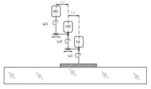
[0023] Embodiment two: see attached image 3 , computer-controlled small tool polishing, revolution speed of planetary motion mechanism, revolution speed of polishing mold, rotation speed of polishing mold, distance L0 between the axis line of motor M0 and the axis line of motor M2, the axis line of motor M1 and the axis of motor M2 The distance L2 between the heart lines is continuously adjustable.

[0024] Computer-controlled small tool polishing, the radius of the polishing mold is 13mm, L2=4.5mm, L0=12mm, W1= 20rpm, W2=140rpm, W0=1.75rpm, according to the actual process conditions, the workpiece is fixed, and the polyurethane circular polishing mold works Pressure 250g, ambient temperature 20 degrees Celsius, cerium oxide polishing powder with a particle size of 1~3μm, according to figure 1 The movement method is to continuously polish a K9 plane for 15 minutes at a fixed point.

[0025] See attached Figure 4 And attached Figure 5 Shown is a schematic diagram of the ...


PUM


Abstract

The invention discloses a method for polishing a computer-controlled gadget. A computer controls the movement of a polishing die, and the action on polishing is realized by controlling the movement route, the movement velocity and the pressure of the polishing die. The method is characterized in that three spindles are arranged; the polishing die is controlled to carry out autorotation around a first spindle and carry out revolution around a second spindle; and a planetary movement mechanism comprising the polishing die, the first spindle and the second spindle is controlled to carry out revolution around a third spindle to control the movement of the polishing die. The method disclosed by the invention can obtain more ideal removal function in the processing area and is suitable for realizing numerical-control polishing.

Description

technical field [0001] The invention belongs to the field of optical processing, and in particular relates to a method for obtaining an ideal removal function in a computer-controlled polishing process. Background technique [0002] Computer-controlled gadget polishing technology CCOS is a new optical processing technology developed in the 1970s. This technology has greatly promoted the development of optical parts manufacturing technology, especially in the large-diameter, high-precision aspheric polishing process, which shows incomparable advantages over traditional methods, and has a tendency to replace manual processing. [0003] CCOS technology uses a polishing mold much smaller in size than the processed parts. Under the control of the computer, according to the measured surface error, the movement route, movement speed and pressure of the polishing mold are changed to grind and polish the surface of the workpiece. In order to control the removal amount of the surface...

Claims


Application Information

Patent Timeline
Patent Type & Authority Patents(China)
IPC IPC(8): B24B29/00
Inventor 郭培基陈曦
Owner SUZHOU UNIV
Why Eureka
Try Eureka