Multiple stage blower and enclosure therefor

A hair dryer and housing technology, applied in the field of multi-stage hair dryers and their housings, which can solve the problems of impeller acceleration, sacrificing optimal pressure and flow characteristics, etc.

Active Publication Date: 2006-07-19
RESMED LTD
View PDF1 Cites 20 Cited by
  • Summary
  • Abstract
  • Description
  • Claims
  • Application Information

AI Technical Summary

Problems solved by technology

The first disadvantage is that in order to switch quickly between IPAP and EPAP, the impeller must be accelerated and decelerated rapidly
Addit

Method used


Image

  • Multiple stage blower and enclosure therefor
  • Multiple stage blower and enclosure therefor
  • Multiple stage blower and enclosure therefor

Examples


Embodiment Construction

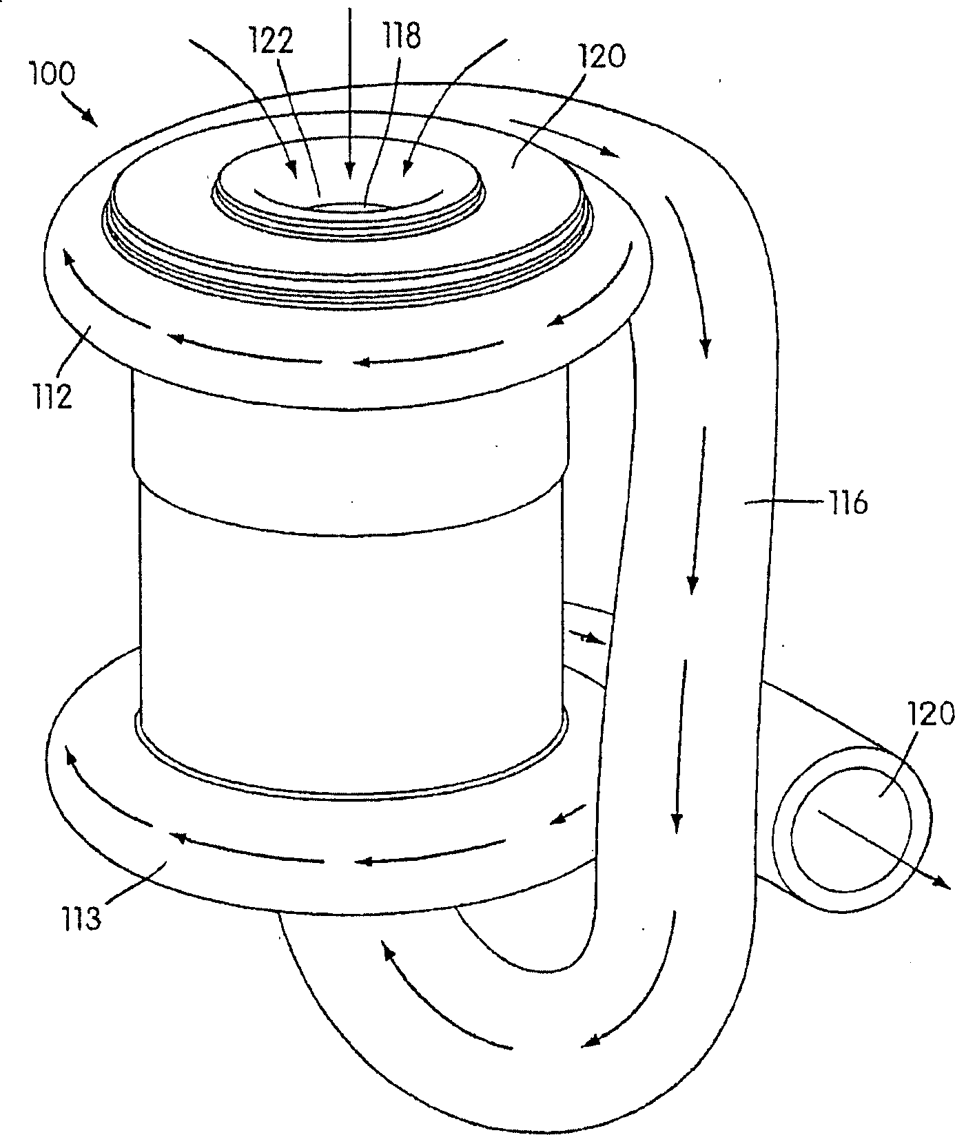
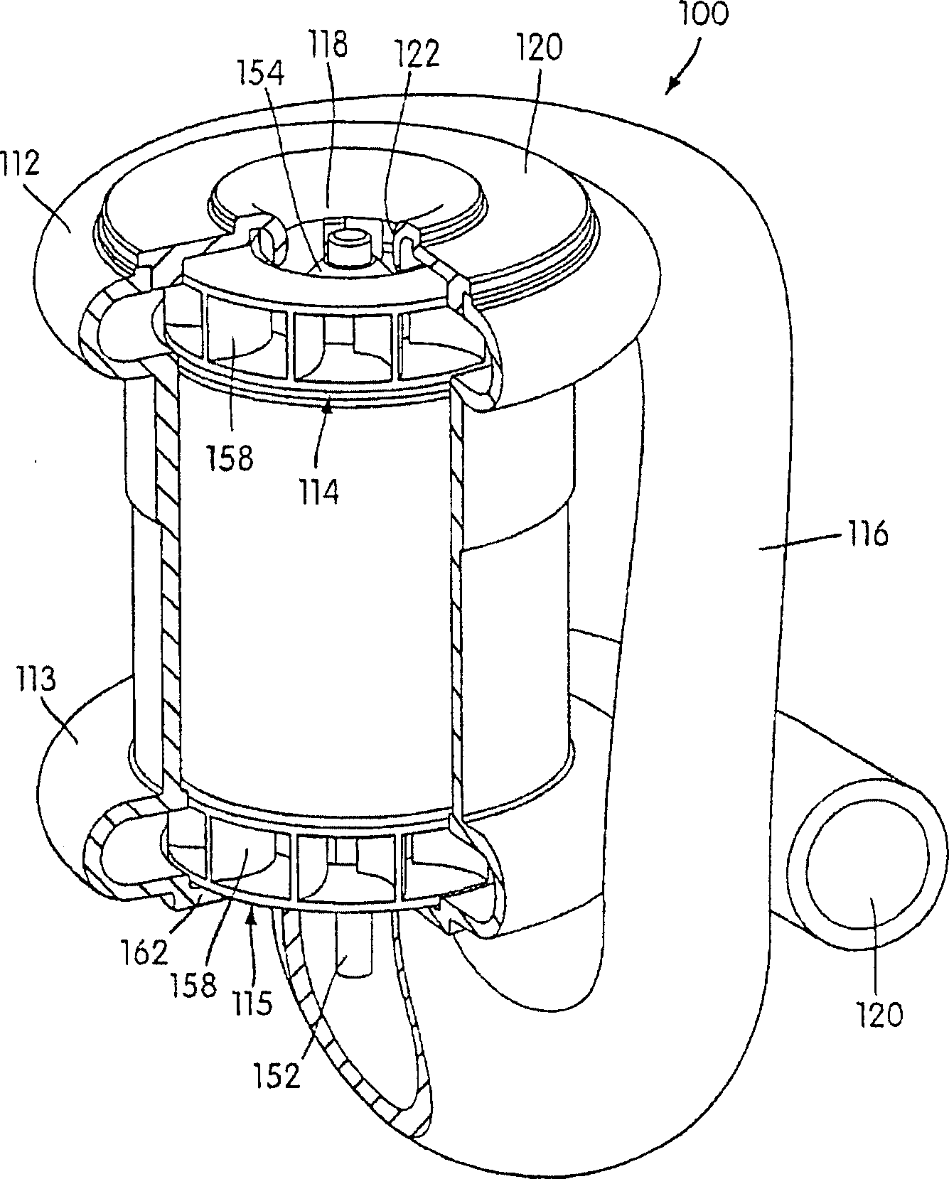
[0049] figure 1 is a perspective view of a dual-head hair dryer 100 according to a first embodiment of the present invention. The blower 100 is generally cylindrical in shape and has an impeller housing or helical tube 112, 113 arranged at each end. Thus, the blower 100 accommodates two impellers 114, 115 which are figure 2 is best viewed in cutaway perspective view.

[0050] Such as figure 1 and figure 2 As shown, two impellers 114 , 115 are arranged in three-dimensional communication with each other through an air flow channel 116 . The air flow channel 116 of the blower 100 has a pipeline extending from the first spiral tube 112 to the second spiral tube 113, and the terminal of the air flow conduit 116 is shaped around the main body of the blower 100 adjacent to the spiral tubes 112, 113 and gradually merges with it, thereby forming A single, complete structure. The air flow channel 116 may have a relatively rigid pipe, for example, the pipe is integrally cast with...


PUM


Abstract

A multiple stage variable speed blower for Continuous Positive Airway Pressure (CPAP) ventilation of patients includes two impellers (114, 115) in the gas flow path that cooperatively pressurize gas to desired pressure and flow characteristics. Thus, the multiple stage blower can provide faster pressure response and desired flow characteristics over a narrower range of motor speeds, resulting in greater reliability and less acoustic noise.

Description

[0001] Cross References to Related Applications [0002] This application is a continuation-in-part of US Application Serial No. 10 / 360,757, filed December 10, 2001, which is hereby incorporated by reference in its entirety. This application also claims the benefit of US Provisional Application No. 60 / 477,063, filed June 10, 2003, and US Provisional Application No. 60 / 477,358, filed June 11, 2003, each of which is hereby incorporated by reference in its entirety. technical field [0003] The present invention relates to a device for providing breathable gas to the human body, which is used for continuous positive airway pressure ventilation for example, obstructive sleep apnea (OSA: Obstructive Sleep Apnea), other respiratory diseases such as emphysema and disorders ( CPAP: Continuous Positive Airway Pressure) treatment; or the application of assisted ventilation. Background technique [0004] CPAP treatment of OSA, a form of non-invasive positive pressure ventilation (NIPP...

Claims


Application Information

Patent Timeline
IPC IPC(8): A61M16/00F04D29/40F04D17/12F04D29/28
CPCA61M16/0057A61M16/0066F04D17/122F04D29/284A61M16/0069A61M16/107A61M2205/42F04D17/12
Inventor 亚历山大·维尔斯蒂芬·安东尼·莱亚戴恩·查理·丘·马丁尼古拉斯·吉尔姆·里德拉里·普克里奇蒂莫西·俊晖·付杰弗里·达尼埃尔·戴利
Owner RESMED LTD
Why Eureka
Try Eureka