Oil separator

A technology of oil-water separation device and separation chamber, which is applied in the direction of liquid separation, separation method, immiscible liquid separation, etc., which can solve the problems of increasing filter resistance, hindering the filtration process of treated water, and clogging, so as to prevent the clogging of meshes , Reduce the blockage of the mesh and reduce the area

Active Publication Date: 2006-07-19
SASAKURA ENG CO LTD
View PDF3 Cites 14 Cited by
  • Summary
  • Abstract
  • Description
  • Claims
  • Application Information

AI Technical Summary

Problems solved by technology

[0004] However, in this prior art, the separation rate of oil can be further improved by forming finer meshes of the coarse-graining elements in the subsequent separation chambers among the separation chambers. However, while the water to be treated contains oil, Also contains solid particles, therefore, causing this solid particle component to clog the meshes of the coarser graining element with fine meshes in the subsequent stage
[0005] That is, in order to increase the separation rate of the oil component, the meshes of the coarser graining elements of the second stage are formed finer, and the meshes of the coarser graining ele

Method used


Image

  • Oil separator
  • Oil separator

Examples


Example Embodiment

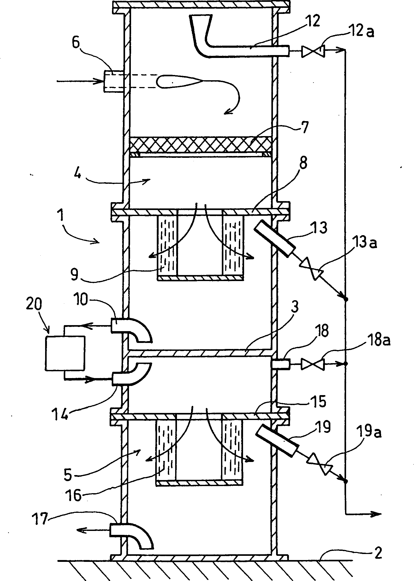
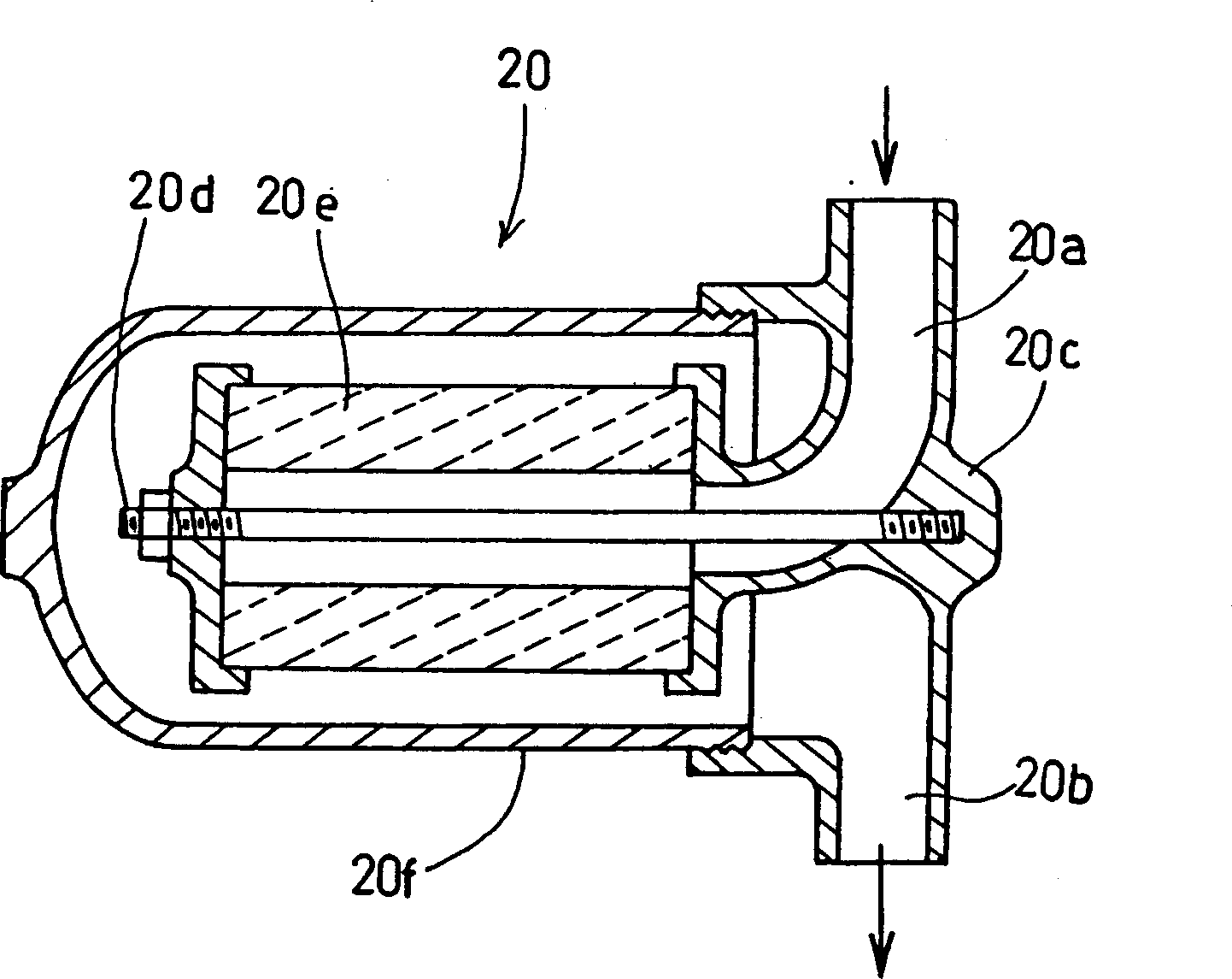
[0031] Below, the embodiment of the present invention is used figure 1 and figure 2 Be explained.

[0032] exist figure 1 In the figure, reference numeral 1 denotes a closed container formed of a vertical cylindrical shape erected on a bottom surface 2 .

[0033] The inside of the airtight container 1 is divided into an upper front-stage separation chamber 4 and a lower rear-stage separation chamber 5 by providing a partition plate 3 .

[0034] On the upper part of the pre-stage separation chamber 4, a supply port 6 for introducing the treated water containing oil and solid particle components into the pre-stage separation chamber 4 is provided. In the tangential direction when viewed in the axial direction of the container 1 , the water to be treated introduced from the supply port 6 can rotate around the axis of the airtight container 1 in the pre-stage separation chamber 4 .

[0035] In addition, a metal mesh layer 7 is provided at a position below the supply port 6 in...


PUM


Abstract

When the oil component in water to be treated is passed for separation through two stages, a coarse-graining element (9) in a front stage separation chamber (4) and a coarse-graining element (16) in a rear stage separation chamber (5), occurrence of clogging in the coarse-graining element (16) in the rear stage separation chamber (5) is avoided to improve the rate of separation of oil component. The water to be treated moving from the front stage separation chamber (4) to the rear stage separation chamber (5) is filtered by a filter element in a filter (20), whereby the solid particle component contained in the water to be treated is separated.

Description

technical field [0001] The present invention relates to an oil-water separator capable of separating the water to be treated into oil and water when oil such as bilge water of a ship is mixed with water to be treated such as waste water. Background technique [0002] In Patent Document 1, which is a prior art, it is proposed that firstly, the water to be treated containing oil is introduced into the pre-stage separation chamber, where it passes through a coarse-graining element with a relatively large mesh. (It is a material that has the function of aggregating and coarsening the extremely fine oil droplets when they pass through the through holes), thereby coarsening the oil droplets and floating and separating them. The water is introduced into the rear-stage separation chamber, where it passes through a coarse-grained element having a mesh finer than that of the coarse-grained element in the preceding-stage separation chamber, whereby the oil droplets are coarsened and se...

Claims


Application Information

Patent Timeline
IPC IPC(8): B01D17/00B01D17/025B01D17/032B01D17/04
Inventor 寺田英敏泽田磐雄足立昌弘桥本馨樱井富康宫地清中岛正希
Owner SASAKURA ENG CO LTD
Why Eureka
Try Eureka