Supercharge Your Innovation With Domain-Expert AI Agents!

Cryostat assembly

A technology for cryostats and components, used in refrigeration components, instruments, electrical components, etc.

Inactive Publication Date: 2006-07-26
OXFORD INSTR SUPERCONDUCTIVITY
View PDF2 Cites 1 Cited by
  • Summary
  • Abstract
  • Description
  • Claims
  • Application Information

AI Technical Summary

Problems solved by technology

[0003] Despite these measures, we found that the output spectrum still shows some noise effects

Method used


Image

  • Cryostat assembly
  • Cryostat assembly
  • Cryostat assembly

Examples


Embodiment Construction

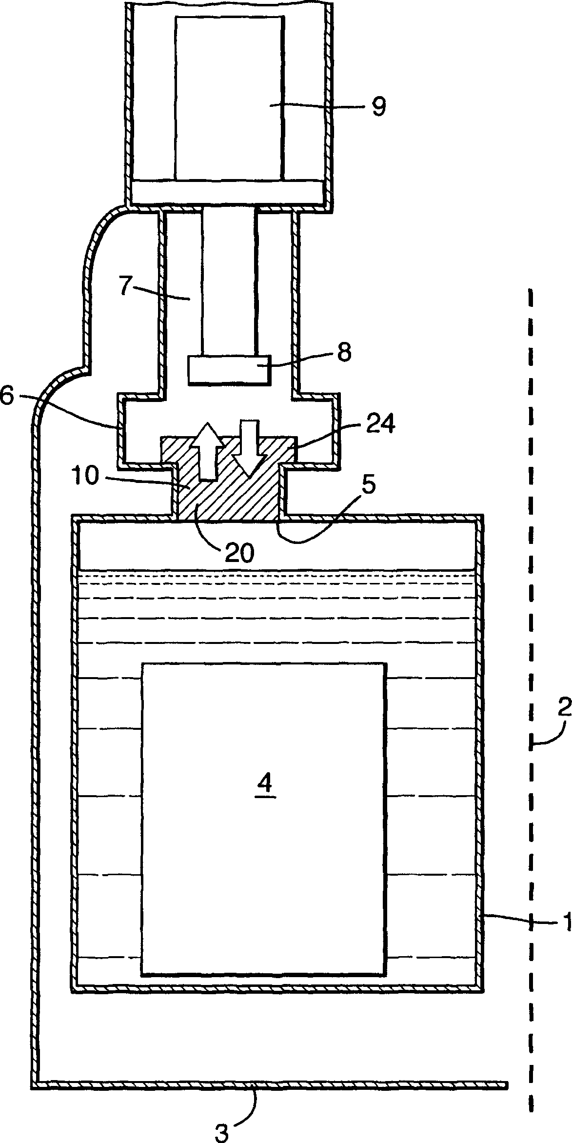
[0019] image 3 The components of a cryostat assembly for NMR are shown schematically. The assembly includes an annular liquid helium container 1 arranged around an axis 2 and defining a bore (not shown). In fact, the container 1 is surrounded by multiple heat shielding devices, and there may be other coolant containers, but for simplicity, only a single 50K heat shielding device 3 is shown in the figure.

[0020] There is a ring-shaped superconducting magnet 4 in the container 1 and it also surrounds the axis 2.

[0021] The upper wall of the container 1 has an aperture 5. The aperture 5 is connected to a cavity 6 or a turret (turret) 7, wherein the cavity 6 has an outwardly extending tube, and the second stage 8 of a two-stage pulse tube refrigerator (PTR) 9 is arranged in the turret 7 . Typically, a part of the wall of the cavity 6 forms a bellows to limit the propagation of vibrations.

[0022] In use, the heat reaching the container 1 causes the liquid helium to boil, and he...


PUM

PropertyMeasurementUnit
diameteraaaaaaaaaa

Abstract

A cryostat assembly comprises a liquid coolant containing vessel (1); a mechanical cooler (9) having at least one cooling stage located above the vessel; and a channel (5) for conveying gaseous coolant from the vessel to the cooling stage where the coolant is condensed in use and then returns through the channel to the vessel. An acoustic wave attenuator (10) is located in the channel (5) for attenuating the passage of acoustic energy originating from the mechanical cooler and propagating through the gaseous coolant, while permitting flow of gaseous coolant to the cooling stage and flow of condensed coolant to the vessel.

Description

Technical field [0001] The present invention relates to a cryostat assembly, which is used, for example, to cool a superconducting magnet or the like to a low temperature. Such components are used, for example, in nuclear magnetic resonance (NMR), magnetic resonance imaging (MRI), ion cyclotron resonance (ICR) and dynamic nuclear polarization (DNP). Background technique [0002] In a typical experiment using this cryostat assembly, typically cooling the superconducting magnet, it is necessary to detect a relatively weak signal emitted by the test sample. It is important to eliminate a large number of noise signals so that the detection signal can be clearly detected. A problem that has occurred in the past is that a mechanical cooler used as a component of the cryostat assembly causes mechanical vibrations, which are transmitted through the wall to the rest of the cryostat assembly. In order to avoid this problem, isolation devices such as bellows have been introduced. Examples o...

Claims


Application Information

Patent Timeline
Patent Type & Authority Applications(China)
IPC IPC(8): F25D31/00F17C13/00F17C13/08F25D19/00G01R33/3815H01F6/04
CPCF25B2500/13F25B2400/17F25D19/00H01F6/04
Inventor 菲利普·亚历山德尔·卡尔欧莱格·基里切克米林德·迪瓦卡尔·阿特雷
Owner OXFORD INSTR SUPERCONDUCTIVITY
Features
  • R&D
  • Intellectual Property
  • Life Sciences
  • Materials
  • Tech Scout
  • Unparalleled Data Quality
  • Higher Quality Content
  • 60% Fewer Hallucinations
Learn More