
Contactless connector

一种非接触、连接器的技术,应用在连接、导电连接、电部件连接等方向,能够解决无法确保高速通信连续性等问题

Inactive Publication Date: 2006-07-26
CHUBU NIHON MARUKO CO LTD
View PDF2 Cites 6 Cited by
  • Summary
  • Abstract
  • Description
  • Claims
  • Application Information

AI Technical Summary

Problems solved by technology

In this switching method, as the data communication rate increases, there are cases where the speed of transferring data is faster than the processing time for switching the optical path, so that the continuity of high-speed communication cannot be ensured

Method used


Image

  • Contactless connector
  • Contactless connector
  • Contactless connector

Examples


Embodiment Construction

[0038] Several preferred embodiments of the present invention are described below with reference to the accompanying drawings.

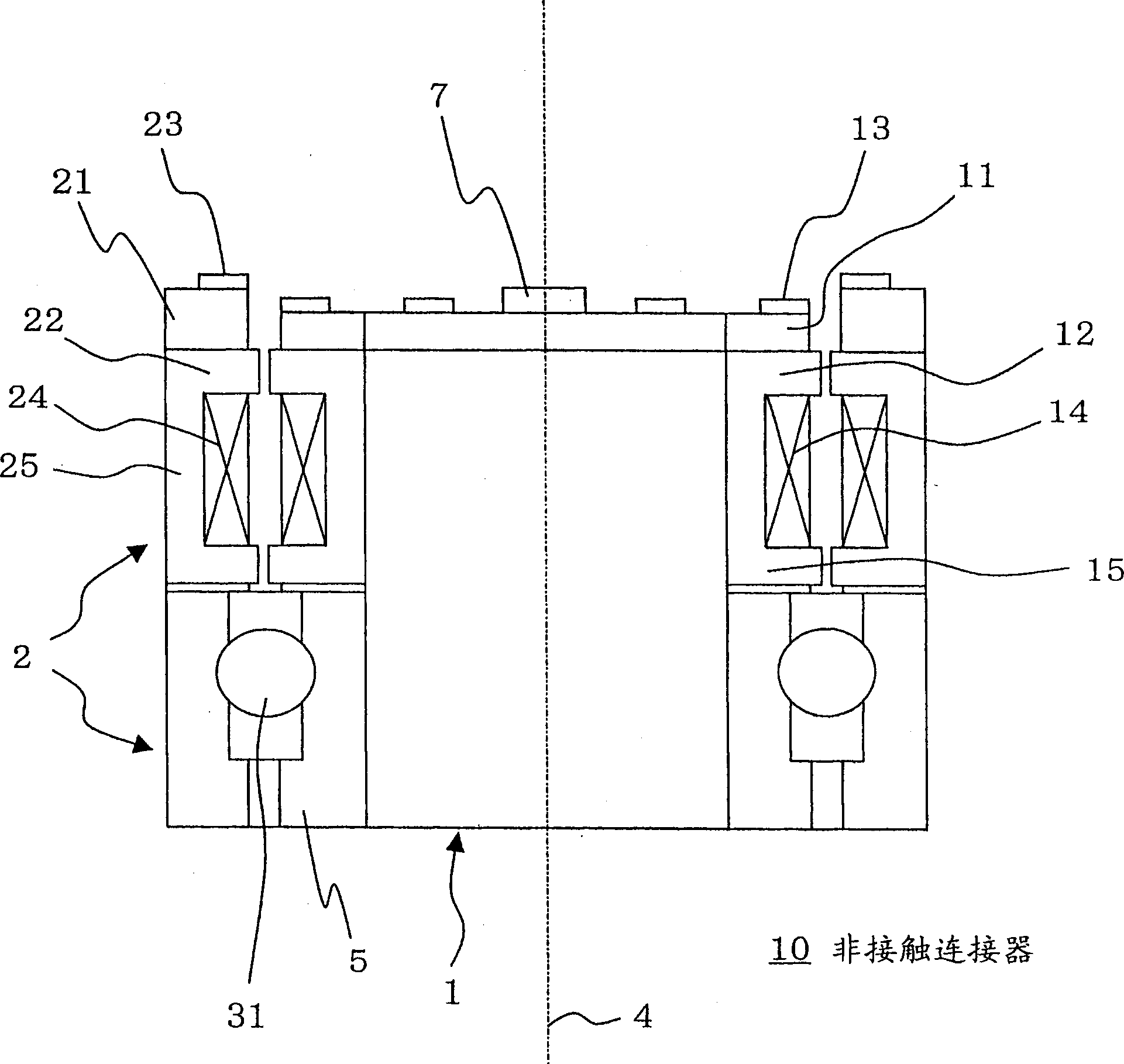
[0039] figure 1 is an example of the non-contact connector 10 to which the present invention is applied, and shows a sectional view in a plane including the rotation axis 4 . Such as figure 1 As shown, in principle, the non-contact connector 10 includes a rotating body 1 and a fixed body 2 . The rotating body 1 is configured so as to be able to rotate about a rotating shaft 4 . The fixed body 2 is arranged and fixed near the rotating body 1 .

[0040] The rotary body 1 includes a rotary side circuit portion 11 , a rotary side holding portion 12 , a rotary side optical element 13 , a rotary side transformer winding 14 , a rotary side transformer core 15 , and a reflector 7 .

[0041] A rotation side circuit section 11 is provided on the upper portion of the rotation body 1 for performing various data processing. For example, when a camera for cap...


PUM


Abstract

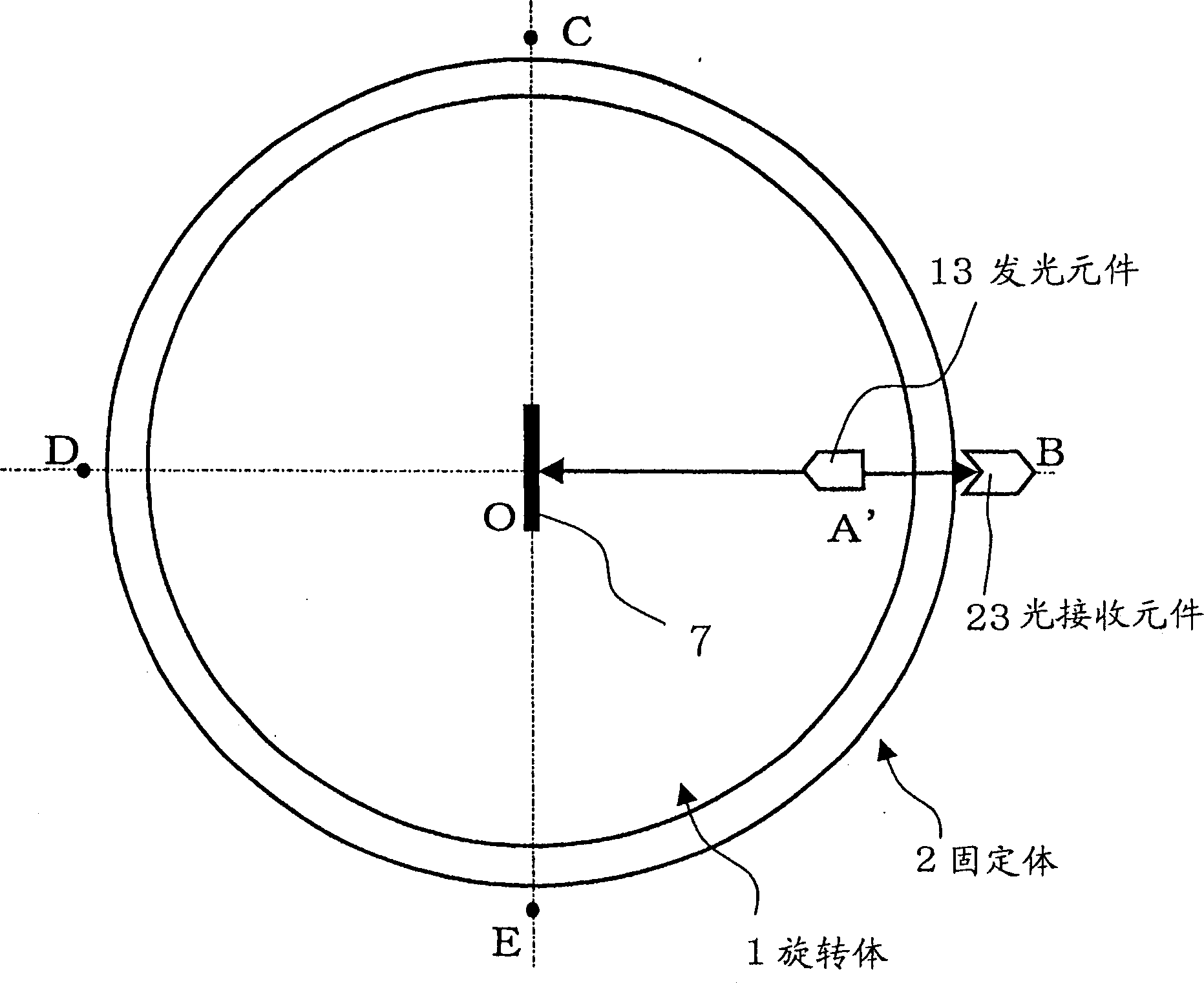
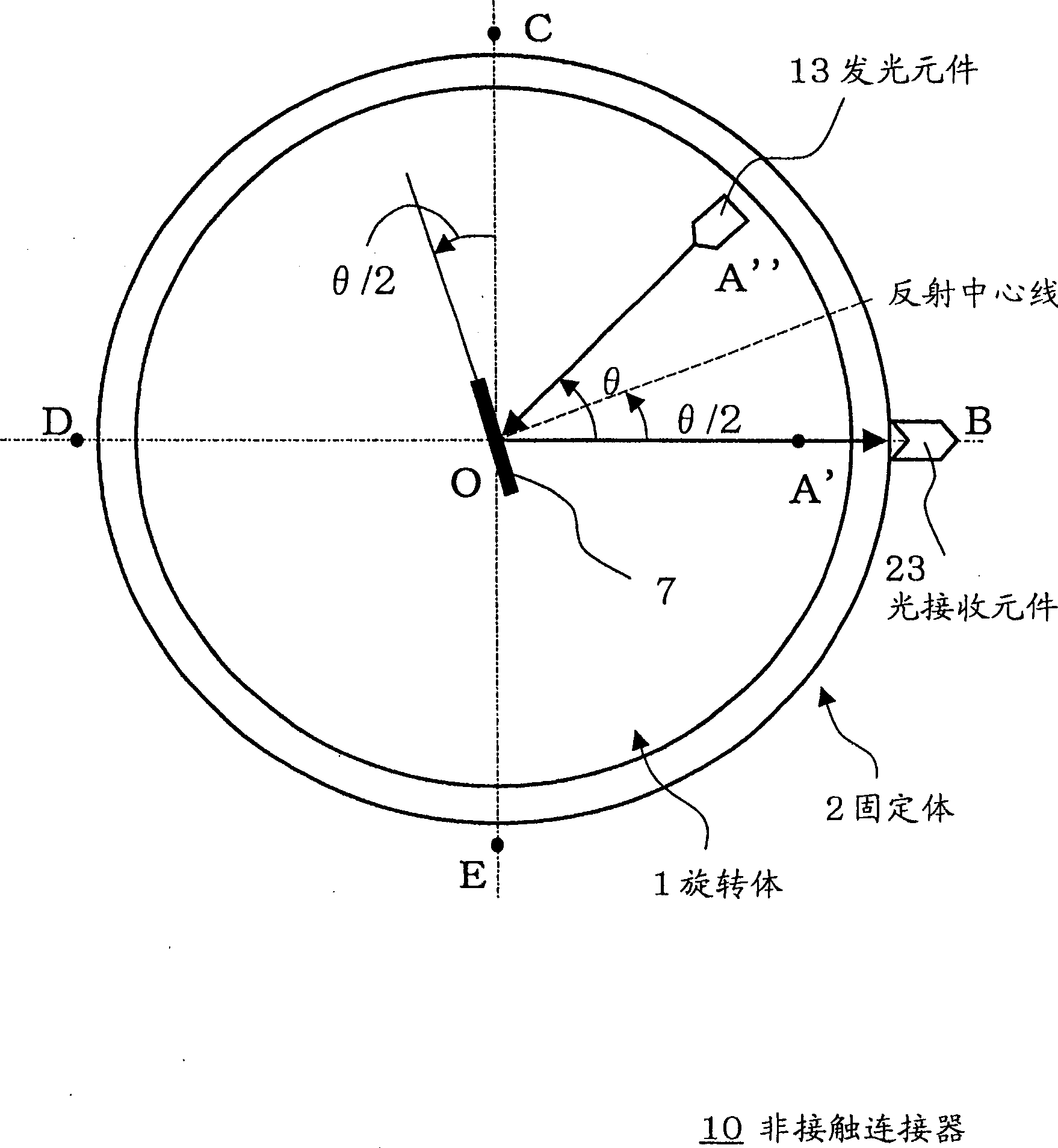
contactless connector. Provides a contactless connector that ensures communication continuity. The non-contact connector includes a rotating side light element on a rotating body that rotates around a rotating shaft and a fixed side light element on a fixed body that is fixed in position; moreover, the rotating body includes a reflector that rotates around the rotating shaft. The two optical elements are constructed such that an optical path is formed between the specific fixed side optical element when the two optical elements are located on the optical line section on which light emitted from the specific rotation side optical element Light is reflected by the reflector. The reflector rotates at half the rotational speed of the rotating body.

Description

technical field [0001] The present invention relates to a non-contact connector for transmitting and receiving data in a non-contact manner, in particular to a non-contact connection between an optical element of a rotating body and an optical element of a fixed body through a reflector arranged on the rotating shaft of a rotating body A contactless connector that sends and receives data. Background technique [0002] In the prior art, data is sent and received between the rotating side and the fixed side. For example, a camera may be set on a rotatable base, and a video signal or the like from the camera may be sent to the fixed-side signal processing section. In this case, the video signal from the camera is sent to the fixed-side signal processing section by directly connecting the camera and the signal processing section using wires. However, with the improvement of wireless signal technology in recent years, it has become possible to perform data transmission and rece...

Claims


Application Information

Patent Timeline
Patent Type & Authority Applications(China)
IPC IPC(8): H01F38/14G02B6/36G02B26/08H01L31/12H04B10/11H04B10/112H04B10/25H04B10/80
CPCG02B6/3604H01R11/30
Inventor 小板桥博行
Owner CHUBU NIHON MARUKO CO LTD
Learn More