Luminance and color separation

A technology of bright color separation and luminance value, which is applied in luminance and chrominance signal processing circuits, color signal processing circuits, etc., and can solve the problem of limited comb filtering direction.

Inactive Publication Date: 2006-07-26
KONINKLIJKE PHILIPS ELECTRONICS NV
View PDF0 Cites 7 Cited by
  • Summary
  • Abstract
  • Description
  • Claims
  • Application Information

AI Technical Summary

Problems solved by technology

However, especially in vertically detailed and/or moving regions, the available comb filtering directions are often very limited due to

Method used


Image

  • Luminance and color separation
  • Luminance and color separation
  • Luminance and color separation

Examples


Embodiment Construction

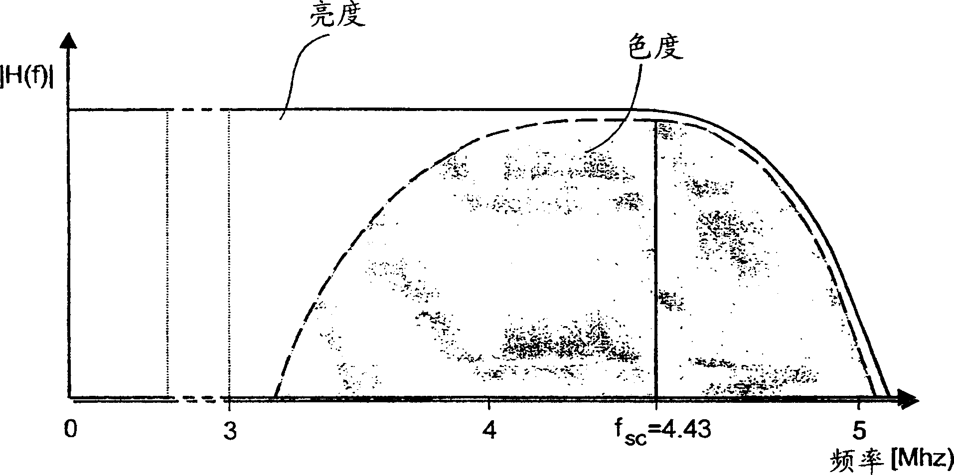
[0070] attached figure 1 The spectrum of a composite PAL video signal is shown schematically.

[0071] In order to understand the issues involved in Y / C separation, one should understand the transmission standards of analog color television signals, such as the PAL, NTSC, SECAM standards described in ITU-R BT.470. For these standards, the requirement to be backward compatible with pre-existing black and white television signals states that the transmission of the chrominance signal (C) must occur within the bandwidth available for grayscale (Y).

[0072] For PAL, the chrominance components U and V are quadrature amplitude modulated onto a 4.43Mhz subcarrier. The resulting one-dimensional spectrum of the composite PAL video signal is at figure 1 shown in . In addition, the sign of the V component, the so-called V-transition, is inverted every other row, thereby reducing the effect of phase errors. The above situation is described more formally in Equation 3, where represe...


PUM


Abstract

A luminance and color separation filter unit (300) for extracting a luminance signal (Y) and two color signals (U, V) from a composite color television signal (CVBS). The filter unit (300) comprises: acquisition means (302) to acquire a first sample of the composite color television signal, corresponding to a first pixel and other samples, corresponding to other pixels in a neighborhood of the first pixel; correlation estimation means (304) to estimate a first set of correlation values representing correlations between the first sample and the respective other samples; penalty estimation means (306) to estimate a second set of penalty values representing relations between the first sample and the respective other samples; computing means (308) to compute a third set of combined values by means of combining respective elements of the first set and the second set; selection means (310) to select a particular sample of the composite color television signal on basis of the corresponding combined value; and decoding means (312) to determine a final luminance value and two color values corresponding to the first pixel, on basis of the first sample and the particular sample.

Description

technical field [0001] The invention relates to a bright color separation filter unit for extracting a luminance signal and two color signals from a composite color television signal, the composite color television signal including a chrominance signal modulated on a sub-carrier located in the spectrum of the luminance signal the high frequency part. [0002] The invention also relates to an image processing device comprising: [0003] - receiving means for receiving a composite color television signal comprising a chrominance signal modulated on a subcarrier located in the high frequency part of the spectrum of the luminance signal; and [0004] - A bright color separation filter unit for extracting a luminance signal and two color signals from a composite color television signal. [0005] The invention furthermore relates to a method for extracting a luminance signal and two color signals from a composite color television signal comprising chrominance signals modulated on ...

Claims


Application Information

Patent Timeline
IPC IPC(8): H04N9/78
CPCH04N9/78H04N9/64
Inventor C·N·科德斯G·德哈安
Owner KONINKLIJKE PHILIPS ELECTRONICS NV
Why Eureka
Try Eureka