Image forming apparatus

一种图像、像载的技术,应用在应用电荷图形的电记录工艺、应用电荷图形的电记录工艺的设备、仪器等方向,能够解决速度变化、重心平衡偏离等问题

Inactive Publication Date: 2006-08-09
RICOH KK
View PDF2 Cites 2 Cited by
  • Summary
  • Abstract
  • Description
  • Claims
  • Application Information

AI Technical Summary

Problems solved by technology

However, due to enlarging the mark or arranging several marks, the center of gravity of the drum drive transmission gear or special parts that set the mark along the vertical direction of the axis will deviate greatly from the axis center of the photosensitive drum, and the center of gravity will deviate from the balance, resulting in speed change

Method used


Image

  • Image forming apparatus
  • Image forming apparatus
  • Image forming apparatus

Examples


no. 1 example

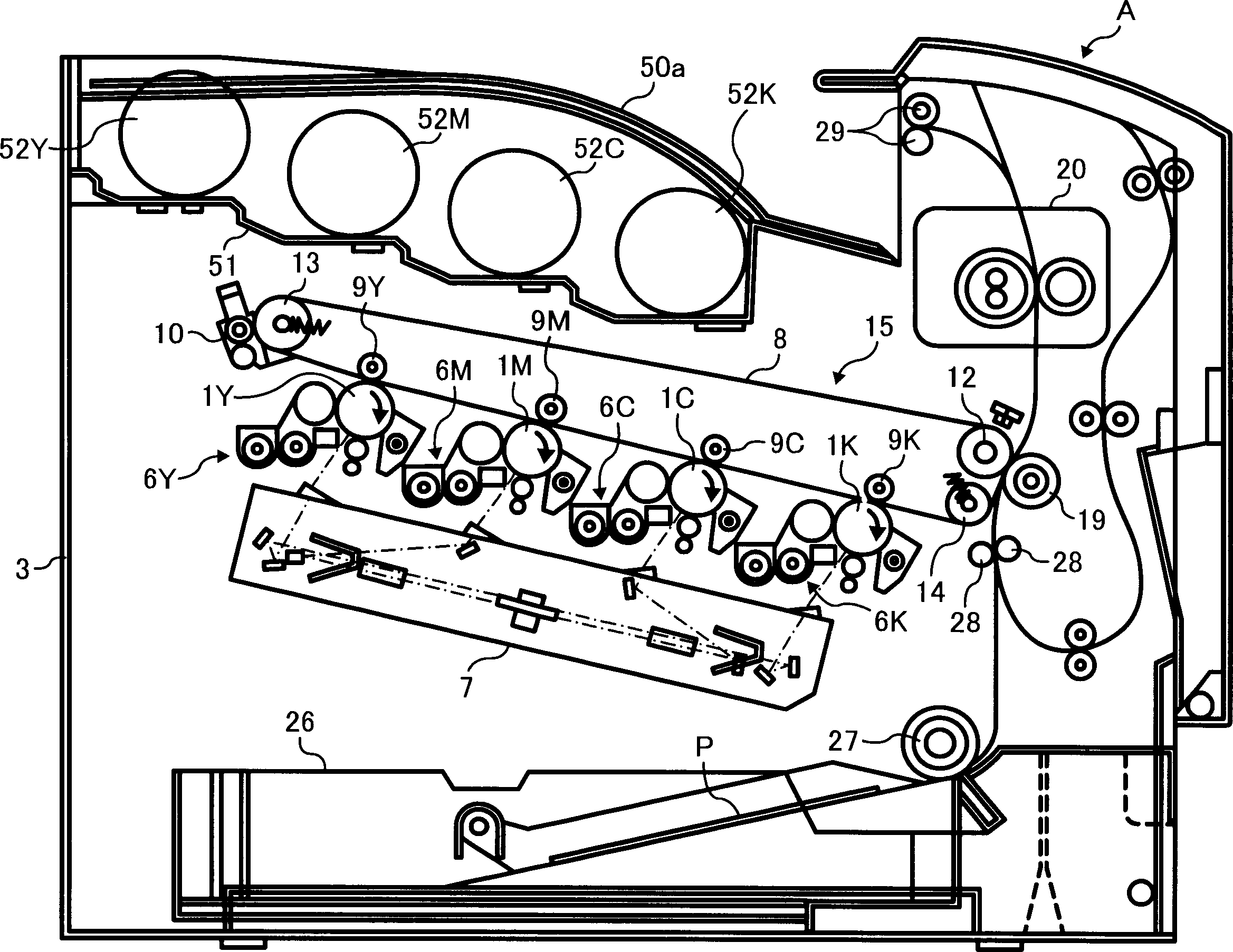
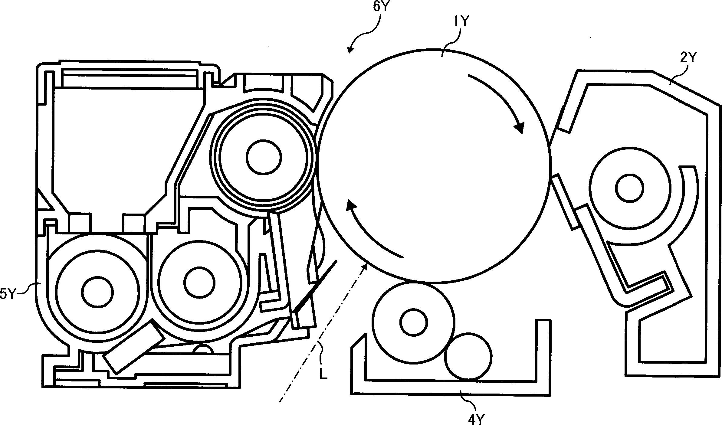
[0043] A first embodiment of the present invention will be described with reference to FIGS. 1 to 6. In the first embodiment, the present invention is applied to a printer (hereinafter abbreviated as "printer") as an electrophotographic multi-color image forming apparatus.

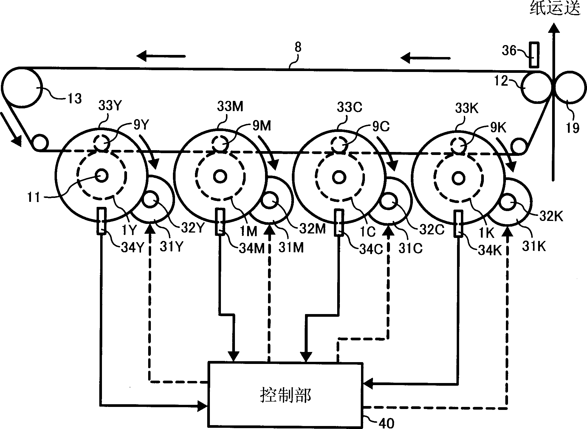
[0044]First, the basic structure of the printer involved in the first embodiment will be described. As shown in FIGS. Motors 31Y, 31M, 31C, 31K, position detection sensor 34, and control means. In the present invention, the added symbol Y represents yellow, C represents cyan, M represents magenta, and K represents black.

[0045] The intermediate transfer belt 8 serves as an intermediate image carrier for temporarily transferring and placing a toner image thereon so as to finally transfer the toner image onto paper P as a transfer material. The photoreceptor drums 1Y, 1M, 1C, and 1K are in contact with the intermediate transfer belt 8 as image carriers. The driving motors 31Y, 31M, 31C, and 31K are used ...


PUM


Abstract

To provide an image forming apparatus with a detector for detecting the position of an image carrier, which can reduce color slurring by restraining the speed variation of the image carrier caused by the detector. The multicolor image forming apparatus A is provided with: a driving means 31 driving and rotating the image carrier 1 through a driving transmission member 33 connected to the image carrier 1; the detectors 41 and 46 arranged on the driving transmission member 33; and a position detection means 34 detecting the rotating position of the image carrier by detecting the detectors 41 and 46 on a plurality of image carriers 1Y to 1K respectively, and also provided with a control means 40 controlling the driving means so as to adjust a phase difference between the plurality of image carriers 1Y to 1K based on a plurality of results of detection detected by the position detection means 34 and 34. It is provided with members 47, 55A and 56B corresponding to the detectors 41 and 46 so that the center of gravity in a vertical direction to the shaft of the driving transmission member 33 may be aligned with the shaft center of the image carrier 1.

Description

technical field [0001] The present invention relates to a multi-color image forming apparatus provided with a plurality of image carriers and used in copiers, printers, etc., and more specifically, it can easily perform color misalignment correction. Background technique [0002] In general, in a multi-color image forming apparatus provided with a plurality of photoreceptor drums as image carriers, variations in the speed changes of the respective photoreceptor drums cause color shifts, which appear in formed images. That is, the drive transmission member is integrated with the photosensitive drum by means of bonding or the like, and the driving force is transmitted to the drive transmission member to drive the photosensitive drum. Mounting eccentricity with respect to the photoreceptor drum and the like occur and are difficult to overcome. Therefore, the axis of each photoreceptor drum, that is, the cycle of the speed change of each photoreceptor drum, is made uniform to a...

Claims


Application Information

Patent Timeline
Patent Type & Authority Applications(China)
IPC IPC(8): G03G15/01G03G15/00G03G21/14
CPCG03G2215/0119G03G15/5008G03G2215/0158G03G15/757G03G15/0178G03G2215/0008G03G15/0194
Inventor 船本宪昭江原让内田俊之
Owner RICOH KK
Why Eureka
Try Eureka