Driving assembly for high-power gas discharge lamps

A technology of gas discharge lamps and discharge lamps, applied in the field of drivers, can solve problems such as time-consuming, expensive, and expensive

Inactive Publication Date: 2006-08-09
KONINK PHILIPS ELECTRONICS NV
View PDF0 Cites 0 Cited by
  • Summary
  • Abstract
  • Description
  • Claims
  • Application Information

AI Technical Summary

Problems solved by technology

[0004] Although low or medium power electronic drivers have been developed for gas discharge lamps, it is not easy to develop high power electronic drivers
For example, it is not easy to scale up existing designs
High power electronic drivers should be developed from the basic drawing board, which is time consuming and expensive
Furthermore, the components to be used in such high power electronic drives include high power components which are expensive

Method used


Image

  • Driving assembly for high-power gas discharge lamps
  • Driving assembly for high-power gas discharge lamps
  • Driving assembly for high-power gas discharge lamps

Examples


Embodiment Construction

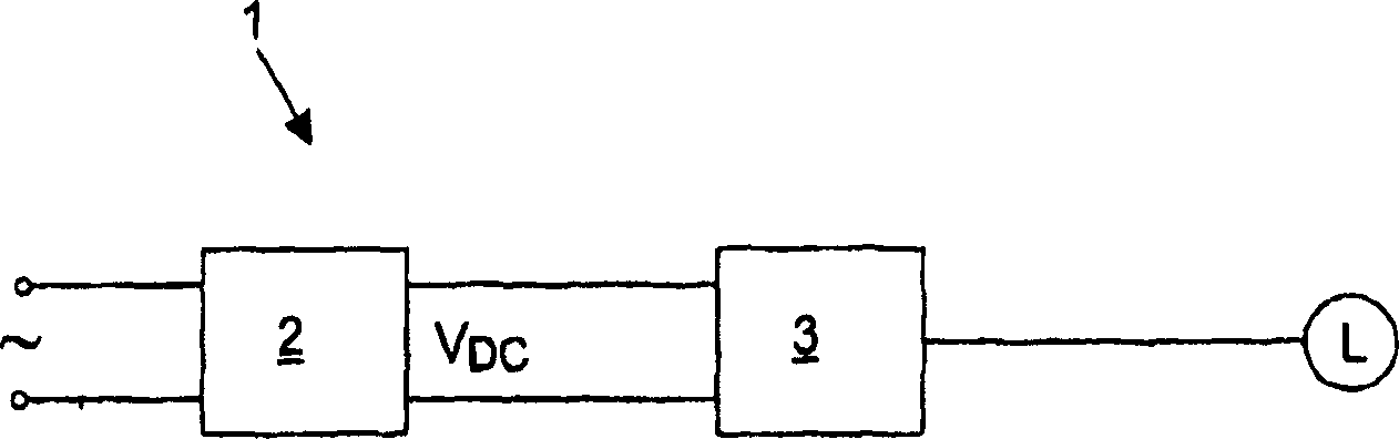
[0015] Figure 1A is a block diagram schematically representing a general two-stage design of a prior art gas discharge lamp driver 1 for a lamp L. FIG. This driver 1 comprises a first stage 2, also denoted pre-regulator, having an input for receiving an AC mains voltage, typically of the order of about 230V. The pre-regulator comprises rectification means for rectifying the input voltage, and an up-transformer for up-converting the rectified voltage into a DC voltage, in particular of the order of 400V or above.

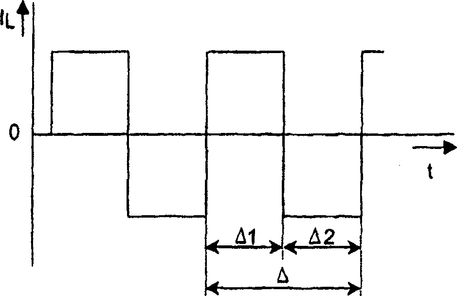
[0016] The second stage 3 has an input receiving a DC voltage from a pre-regulator and has an output connected to a lamp L. This second stage, also denoted forward commutator, is designed to generate an alternating DC current at its output, ie a current of substantially constant magnitude but with alternating direction. Figure 1B The shape of the current IL flowing through the lamp L is schematically represented as a function of time t, here any superimposed high-...


PUM


Abstract

A driver assembly (10) for driving a high-power gas discharge lamp (L) comprises a plurality of at least two low-power lamp drivers (1 A, 1B, 1C) having their respective output terminals coupled in parallel, each individual driver (l A, 1B, 1C) being designed for generating a commutating DC-current at its respective output terminal, the assembly (10) comprising synchronisation means for synchronising the output currents of the individual drivers (1 A, 1 B, 1 C).

Description

technical field [0001] The present invention relates generally to the field of drivers for gas discharge lamps, and in particular to high intensity discharge (HID) lamps. Background technique [0002] Typically, gas discharge lamps are driven by CuFe ballasts. Furthermore, electronic drives have been developed which offer the advantages of higher operating frequencies and improved efficiency. [0003] Gas discharge lamps are designed for a specific nominal power and drivers for these lamps must be designed for the required power rating. To date, electronic drives are available with nominal powers of eg 50W, 150W, 250W, 400W, 600W. Gas discharge lamps with very high powers, eg 1800 W, are still currently driven by CuFe ballasts. However, it is desirable that these lamps are also driven by electronic drivers. Therefore, there is a need for high power electronic drivers for gas discharge lamps, especially HID lamps. [0004] Although low or medium power electronic drivers ...

Claims


Application Information

Patent Timeline
Patent Type & Authority Applications(China)
IPC IPC(8): H05B41/288
CPCH05B41/288
Inventor D·H·J·凡卡斯特伦
Owner KONINK PHILIPS ELECTRONICS NV
Why Eureka
Try Eureka