Universal vacuum cleaner telescopic tube

A telescoping tube and vacuum cleaner technology, which is applied in the direction of vacuum cleaners, suction hoses, cleaning equipment, etc., can solve the problem that the axial direction of the vacuum tube cannot form a certain angle and is inconvenient

Inactive Publication Date: 2006-08-23
沈盘根
View PDF3 Cites 6 Cited by
  • Summary
  • Abstract
  • Description
  • Claims
  • Application Information

AI Technical Summary

Problems solved by technology

[0003] The applicant found that although various vacuum cleaners bring convenience to the user's routine vacuuming operation due to the adjustable length of the suction pipe, however, since the axial direction of the suction pipe cannot form a certain angle, it is difficult to clean the bottom of the cabinet or the like. It is very inconvenient to have to bend over and stand on tiptoes when performing vacuuming operations such as close-to-floor vacuuming operations or high-hanging vacuuming operations such as cabinet tops.

Method used


Image

  • Universal vacuum cleaner telescopic tube
  • Universal vacuum cleaner telescopic tube
  • Universal vacuum cleaner telescopic tube

Examples


Embodiment 1

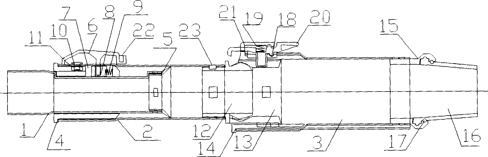
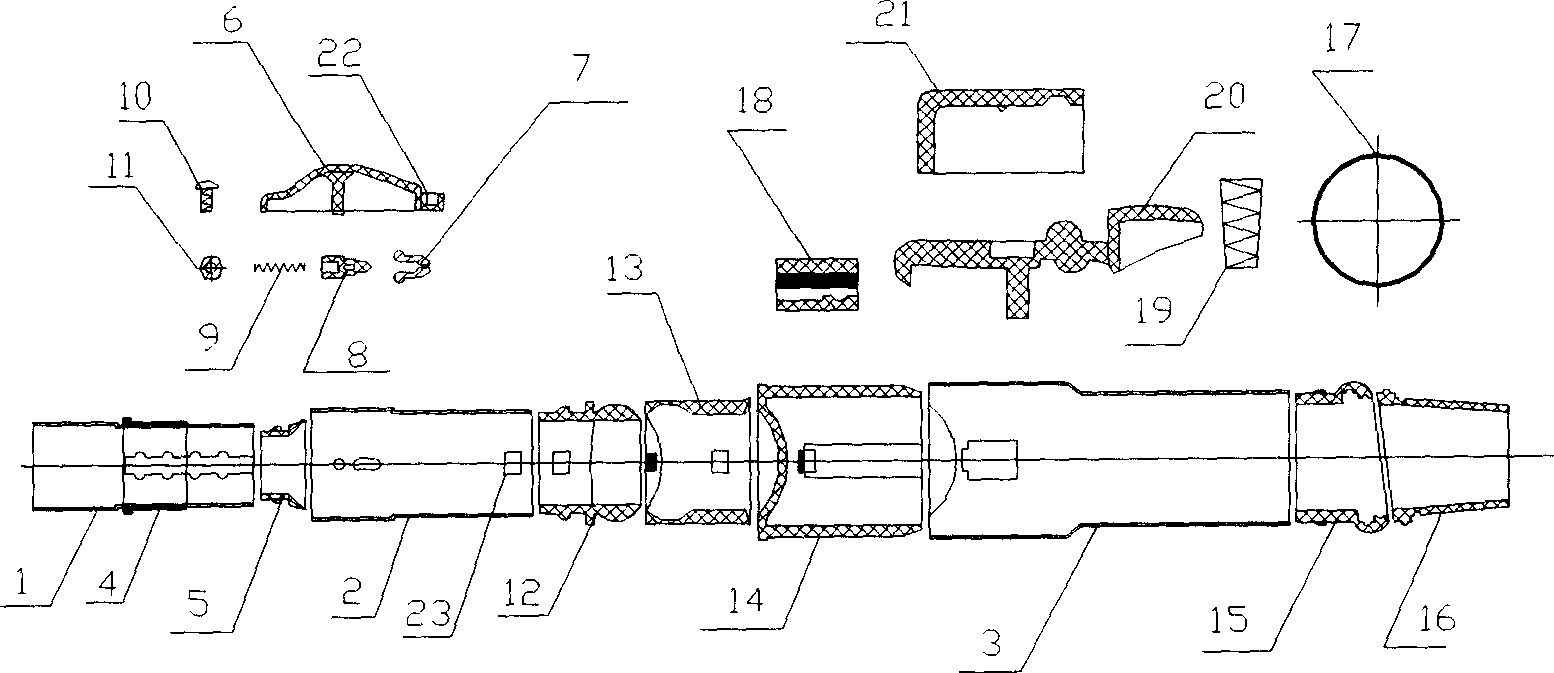
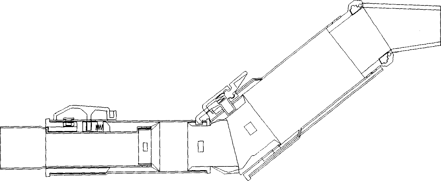
[0013] The telescoping tube of the universal vacuum cleaner of the present embodiment is as follows: figure 1 , 2 , 3, the main parts are as follows: core tube 1, inner tube 2, outer tube 3, small inner bushing 4, sealing ring 5, button push plate 6, movable locking block 7, movable slider 8, spring 9, screw 10. Nut 11, ball hinge head 12, ball hinge sleeve 13, large inner bushing 14, elbow movable connection seat 15, elbow movable connection head 16, O-ring 17, button lock seat 18, tapered Spring 19, button lock 20, button lock cover 21, outer tube indentation locking hole 22, bending locking hole 23.

[0014] The core pipe 1 is telescopically inserted into the inner pipe 2 through the small inner bushing 4 fixed on the flaring section of the inner pipe 2 . The second locking mechanism that button push plate 6, movable lock block 7, movable slide block 8, spring 9, screw 10, nut 11 constitute is installed in the flaring section of inner pipe, wherein movable lock block 7 an...


PUM


Abstract

The present invention relates to a kind of telescopic tube locking mechanism in improved structure for vacuum cleaner, and belongs to the field of household appliance technology. The universal telescopic tube locking mechanism for vacuum cleaner includes at least two sections of telescopic inner tube and outer tube with locking mechanism in between. The improved structure has spherical hinge pair comprising one hinge ball in one end of the inner tube and one hinge sleeve inserted inside the outer tube. After the inner tube is withdrawn from the outer tube, the axial inclination angle between two tubes may be regulated through the spherical hinge structure for convenient dust collecting operation in different positions.

Description

technical field [0001] The invention relates to a vacuum cleaner component, in particular to a structural improvement of a vacuum cleaner telescopic tube, which belongs to the technical field of household appliances. Background technique [0002] In order to meet the requirements of existing vacuum cleaners for adjusting the length of the suction pipe, the suction pipe is usually composed of an outer pipe and a telescopic inner pipe inserted therein, and a locking mechanism is installed between the inner and outer pipes. When in use, after the locking mechanism is released, the inner tube can be retracted as required to obtain a suitable length, and then the inner and outer tubes can be locked. There are many types of locking mechanisms and related inner and outer tube structures, and their typical structures can be found in related patent application documents such as CN200510038703.4, CN200420079535.4, and CN03221741.2. [0003] The applicant found that although various v...

Claims


Application Information

Patent Timeline
Patent Type & Authority Applications(China)
IPC IPC(8): A47L9/24
CPCA47L9/244A47L9/242
Inventor 沈盘根
Owner 沈盘根
Why Eureka
Try Eureka