Ball grinding machine dust suction device for ceramic tile machining

A technology for a vacuum cleaner and a grinding machine, which is applied in the directions of removing smoke and dust, cleaning methods and utensils, cleaning hollow objects, etc. Efficiency and convenience, easy to use, flexible and adjustable structure

Active Publication Date: 2018-10-19
周昱行
View PDF8 Cites 0 Cited by
  • Summary
  • Abstract
  • Description
  • Claims
  • Application Information

AI Technical Summary

Problems solved by technology

[0002] In the process of ceramic tile processing, it is necessary to use a ball mill to grind materials. During use, some processing waste is often left on the inner wall of the cylinder of the ball mill, which will affect the next processing. Therefore, it is necessary to clean the inside. When cleaning It needs to be vacuumed. The existing dust collection device cannot adjust the stroke of the dust suction mechanism according to the length of the ball mill when in use, and cannot perform dust suction for ball mills of different models and specifications, which reduces the practicability during use, and It cannot adjust the distance between the dust suction port and the inner wall of the ball mill, and cannot make the cleaning brush close to the inner wall of the ball mill, which reduces the efficiency and convenience of dust collection. Its structure is rigid and cannot be adjusted.

Method used


Image

  • Ball grinding machine dust suction device for ceramic tile machining
  • Ball grinding machine dust suction device for ceramic tile machining
  • Ball grinding machine dust suction device for ceramic tile machining

Examples


Embodiment Construction

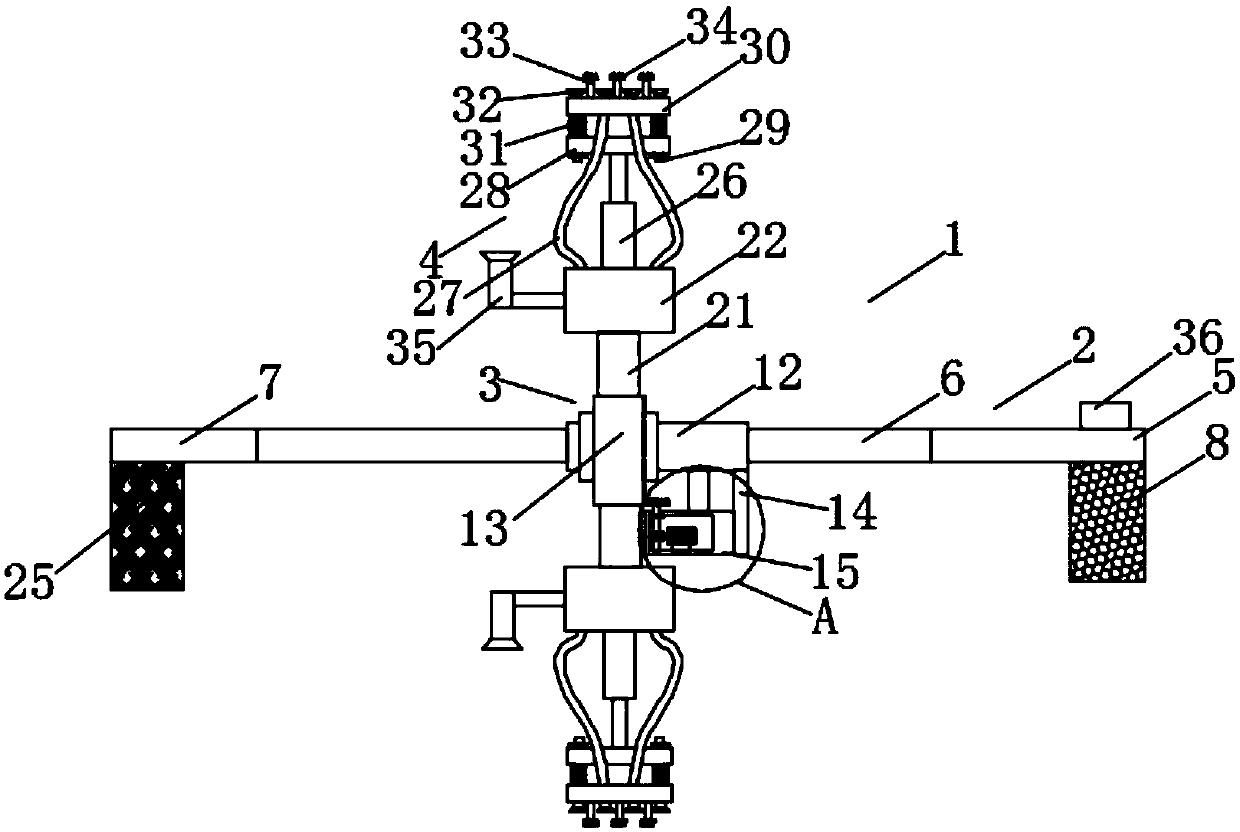
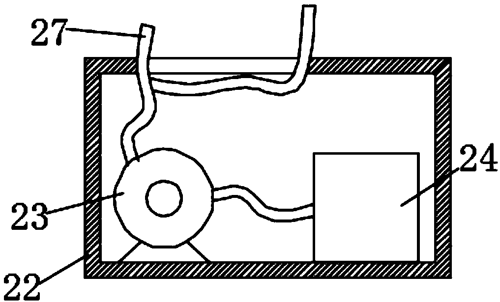
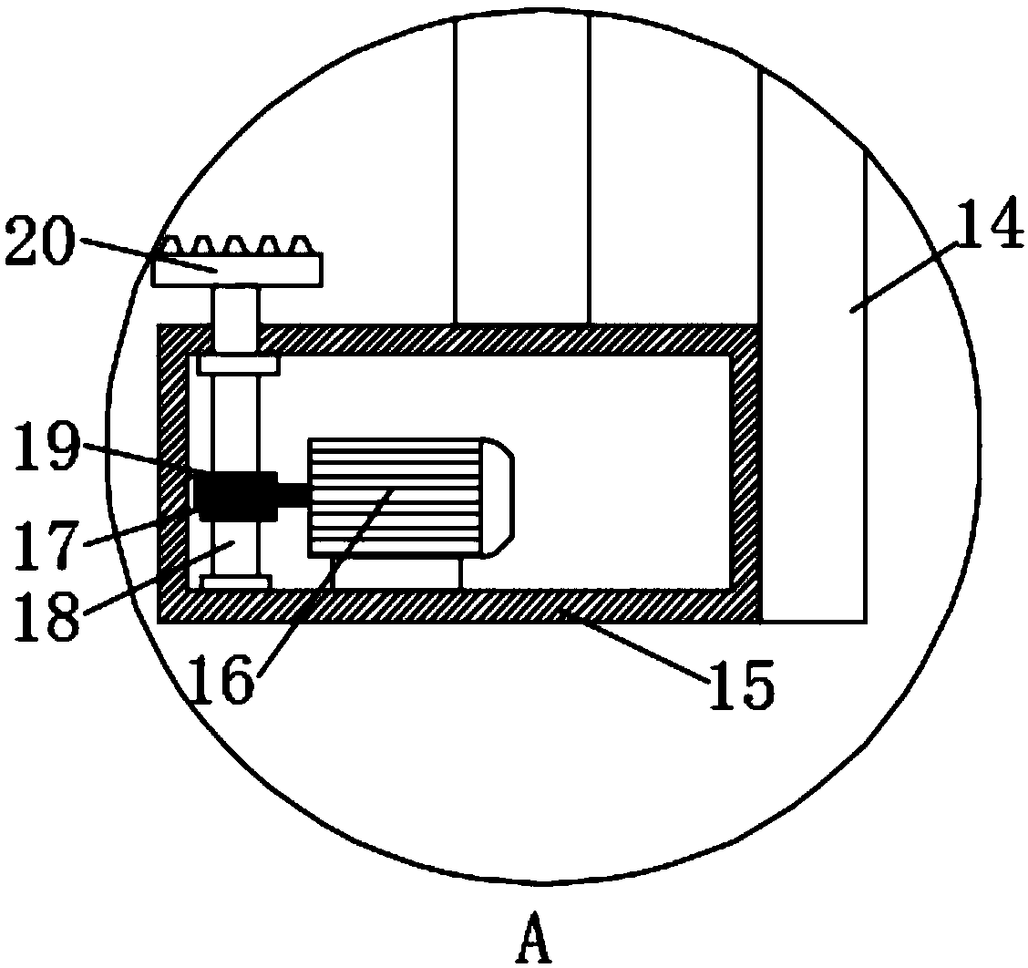
[0020] like Figure 1-4 As shown, this specific embodiment adopts the following technical solutions: a ball mill dust collection device for ceramic tile processing, including a dust collection device body 1, and the dust collection device body 1 is composed of a support mechanism 2, a rotating mechanism 3 and a dust collection mechanism 4 , the support mechanism 2 is composed of a first fixed plate 5, a grafted sliding rod 6, a second fixed plate 7, a first fixed electromagnet 8, a first electric telescopic rod 9, a connecting plate 10, a distance adjustment push rod 11 and a moving slide Composed of columns 12, one end of the first fixed plate 5 is threadedly connected with two grafted slide bars 6, and the ends of the two grafted slide bars 6 away from the first fixed plate 5 are threaded with a second fixed plate 7, so The bottom of the first fixed plate 5 is fixedly connected with a first fixed electromagnet 8, the bottom of the second fixed plate 7 is fixedly connected wi...


PUM


Abstract

The invention discloses a ball grinding machine dust suction device for ceramic tile machining. The ball grinding machine dust suction device comprises a dust suction device body. The dust suction device body is composed of a supporting mechanism, a rotation mechanism and a dust suction mechanism. The supporting mechanism is composed of a first fixing plate, a grafting sliding rod, a second fixingplate, a first fixing electromagnet, a first electric telescopic rod, a connecting plate, a distance adjusting push rod and a movable sliding column. The ball grinding machine dust suction device iscompact in structure, and is conveniently used for ball grinding machine dust suction; through the arrangement of the supporting mechanism and the grafting sliding rod, the stroke of the dust suctionmechanism can be adjusted according to the length of a ball grinding machine during usage, the ball grinding machine dust suction device can conduct dust suction for ball grinding machines different in type and specification, and using practicability is improved; and through the arrangement of the rotation mechanism and a second electric telescopic rod, the distance between a dust suction port andthe inner wall of a ball grinding machine can be adjusted through the ball grinding machine dust suction device, a cleaning brush can be closely attached to the inner wall of the ball grinding machine, the dust suction efficiency and convenience are improved, and the ball grinding machine dust suction device is flexible and adjustable in structure and convenient and fast to use.

Description

Technical field: [0001] The invention relates to the technical field of tile processing, in particular to a ball mill dust suction device for tile processing. Background technique: [0002] In the process of ceramic tile processing, it is necessary to use a ball mill to grind materials. During use, some processing waste is often left on the inner wall of the cylinder of the ball mill, which will affect the next processing. Therefore, it is necessary to clean the inside. When cleaning It needs to be vacuumed. The existing dust collection device cannot adjust the stroke of the dust suction mechanism according to the length of the ball mill when in use, and cannot perform dust suction for ball mills of different models and specifications, which reduces the practicability during use, and It cannot adjust the distance between the dust suction port and the inner wall of the ball mill, and cannot make the cleaning brush close to the inner wall of the ball mill, reducing the efficie...

Claims


Application Information

Patent Timeline
Patent Type & Authority Applications(China)
IPC IPC(8): B02C17/18B02C17/10B08B9/087B08B15/04
CPCB02C17/10B02C17/18B08B9/087B08B15/04
Inventor 周昱行
Owner 周昱行
Why Eureka
Try Eureka