X-ray contrast medium transport device in root-canal

A delivery device and contrast agent technology, applied in medical science, dental radiology diagnosis, surgery, etc., can solve problems such as unseen technologies and solutions

Inactive Publication Date: 2006-08-23
WUHAN UNIV
View PDF0 Cites 3 Cited by
  • Summary
  • Abstract
  • Description
  • Claims
  • Application Information

AI Technical Summary

Problems solved by technology

Aiming at this problem, there is no special techn

Method used


Image

  • X-ray contrast medium transport device in root-canal
  • X-ray contrast medium transport device in root-canal

Examples


Embodiment Construction

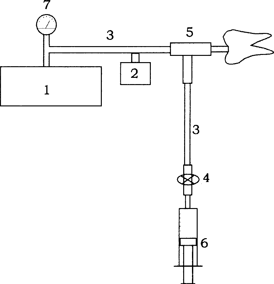
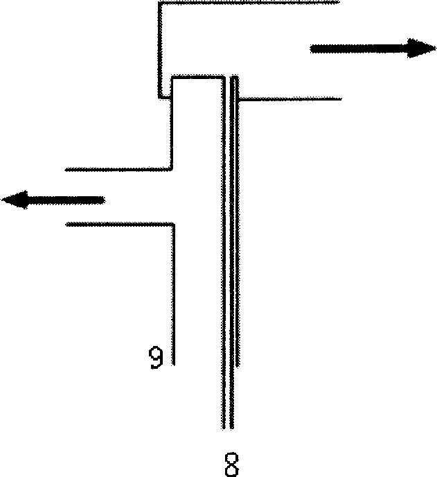
[0013] see figure 1 , figure 2 , the root canal X-ray contrast agent delivery device provided by the present invention is mainly composed of a rotary vane vacuum pump 1, a filter element 2 preventing liquid from being sucked into the vacuum pump 1, a connecting tube 3 (preferably made of transparent hard plastic), a Composed of a through valve 4, a contrast medium delivery head 5, a syringe 6 for storing contrast medium, and a vacuum pressure gauge 7. The rotary vane vacuum pump 1 is connected to the vacuum pressure gauge 7 through a transparent hard plastic connecting pipe 3, and the ultimate vacuum pressure of the rotary vane vacuum pump 1 should be ≤20mba (2×10 3 Pa), when the device is running, it should ensure that the effective vacuum range reaches ≤30mba (3×10 3 Pa), the vacuum pressure gauge 7 shows that the pressure range is 0~-0.1MPa. The vacuum pump 1 is connected to the filter element 2 that prevents liquid from being sucked into the vacuum pump through a trans...


PUM


Abstract

The present invention relates to one device for automatically conveying X-ray contrast medium into root canal in contrast examination of root canal. The device consists of a sliding vane rotary vacuum pump, a filter element to avoid the sucking of liquid into the vacuum pump, a transparent hard plastic connecting pipe, a valve with switch, a contrast medium feeding head, a injector for storing contrast medium and a vacuum meter. By means of negative pressure and special conveying head, the device leads X-ray contrast medium to the whole root canal system with less bubbles so as to reach excellent root canal contrast examination effect.

Description

technical field [0001] The invention belongs to the technical field of medical equipment, and relates to a device for automatically transporting an X-ray contrast agent into a root canal system, and realizes the X-ray contrast examination of the root canal system through the device. Background technique [0002] The root canal system is located in the tooth body, including the main root canal, side branch root canal, accessory root canal, root canal confinement, root canal communication branches, apical furcations and divergences, etc., and its anatomy varies from tooth to tooth and is very complex. Root canal therapy is the basic technology for the treatment of modern endodontics and periapical diseases. It uses various mechanical and chemical methods to completely remove the infected substances in the entire root canal system, and then tightly seals the entire root canal system, thereby To achieve a radical cure for pulp and periapical diseases. Therefore, understanding t...

Claims


Application Information

Patent Timeline
IPC IPC(8): A61B19/00A61B6/14A61C19/00
Inventor 范兵范伟杨俊高原闵艺
Owner WUHAN UNIV
Why Eureka
Try Eureka