Tool mounting device for turning center

一种安装装置、工具的技术,应用在工具夹、车削设备、车床等方向,能够解决不能实现无液压化、车削加工中心困难、不能实现节能和节省资源等问题,达到节省资源、实用性优异的效果

Inactive Publication Date: 2006-08-30
OM MFG CO LTD
View PDF3 Cites 4 Cited by
  • Summary
  • Abstract
  • Description
  • Claims
  • Application Information

AI Technical Summary

Problems solved by technology

[0004] Therefore, since a hydraulic cylinder device is required, no hydraulics can be realized, and energy saving and resource saving cannot be realized
[0005] On the other hand, for example, simply implementing the wedge mechanism (Japanese Patent Laid-Open No. 2004-202659 ) developed by the applicant, which can resist a large cutting force even if an air cylinder device is used, etc., in a turning center, it is necessary to be able to Rotationally clamping and fixing, since it is necessary to constitute a common clamping mechanism for clamping and fixing the rotating tool and the turning tool, it is relatively difficult for the turning machining center

Method used


Image

  • Tool mounting device for turning center
  • Tool mounting device for turning center
  • Tool mounting device for turning center

Examples


Embodiment Construction

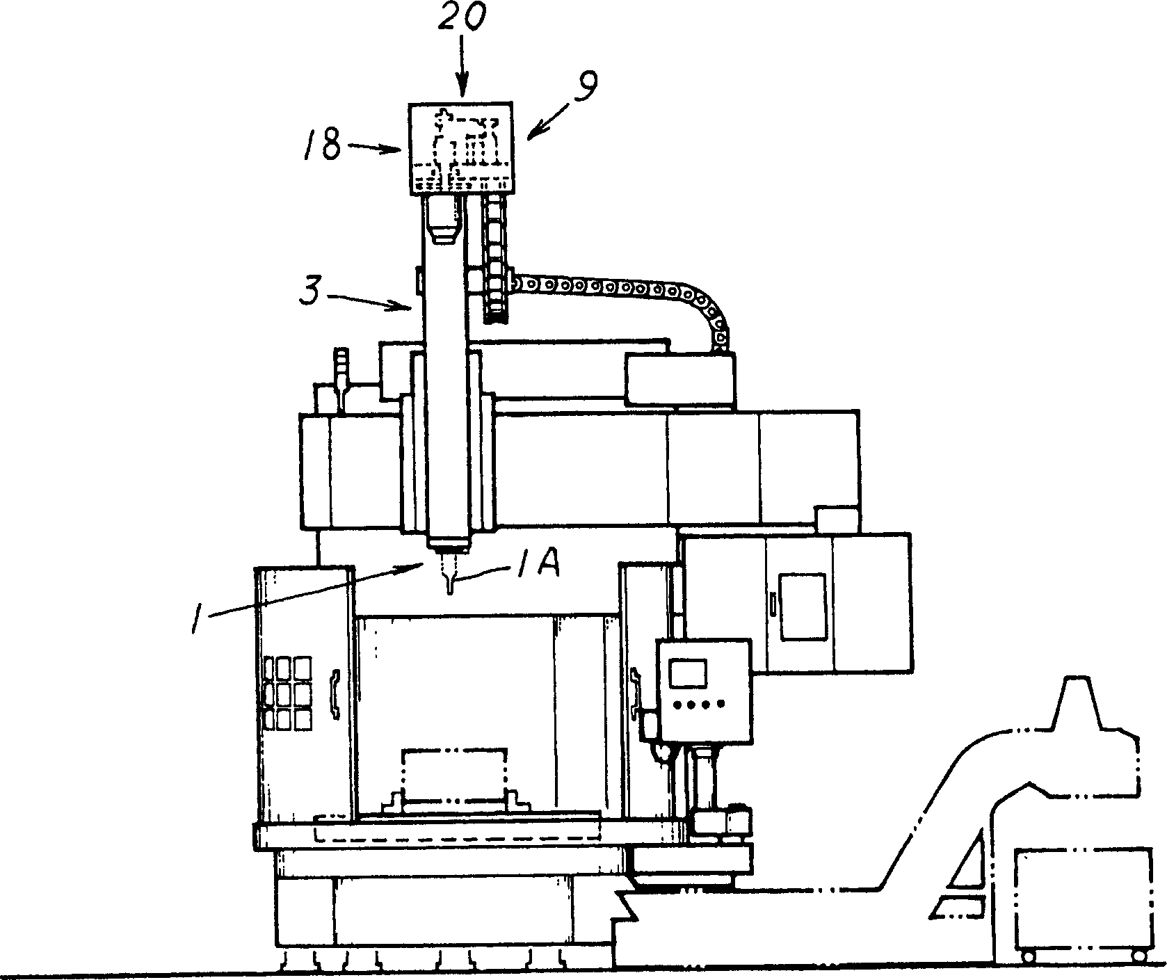
[0041] Preferred embodiments of the present invention (how to carry out the present invention) and functions of the present invention will be briefly described with reference to the drawings.

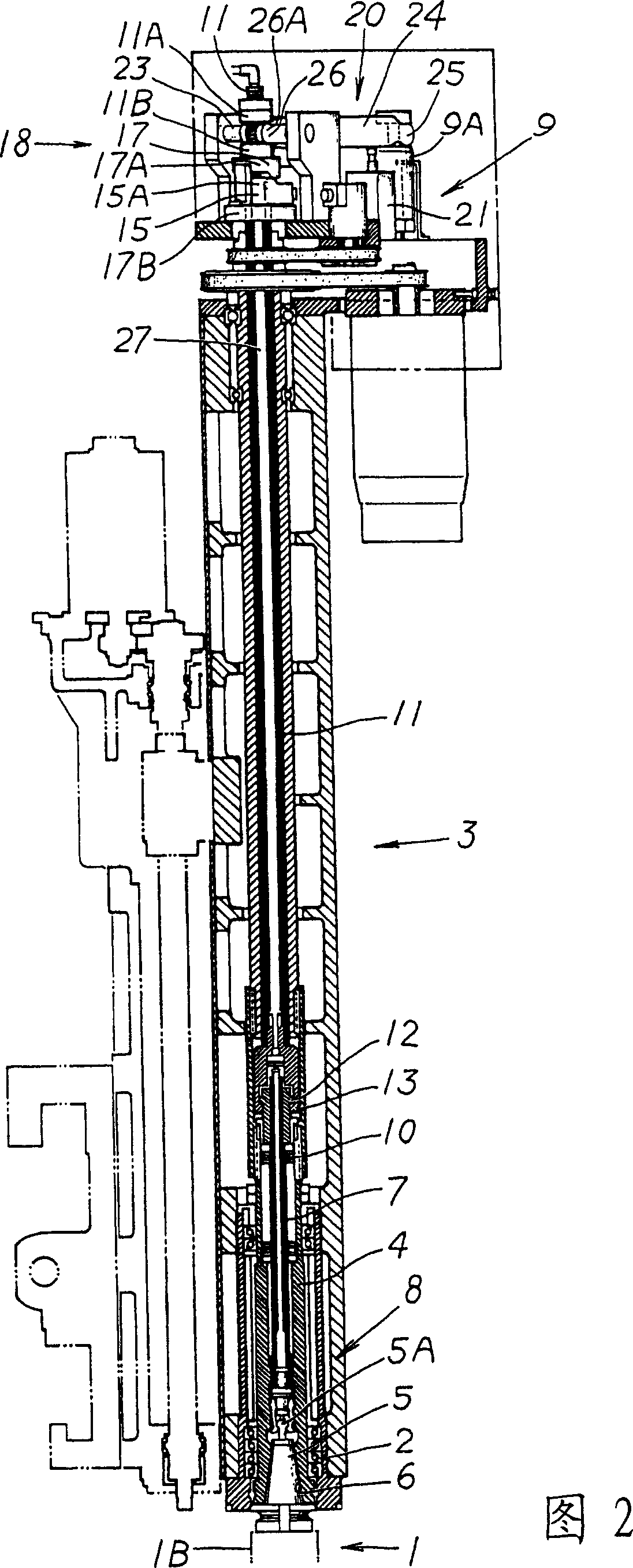
[0042] When the clamping mechanism 8 performs the clamping action and the pull rod 7 is pulled, the taper shank 5 of the tool 1 is pulled closer and engages with the mounting engaging portion 6 provided on the main shaft 4, so that the tool 1 is clamped and fixed.

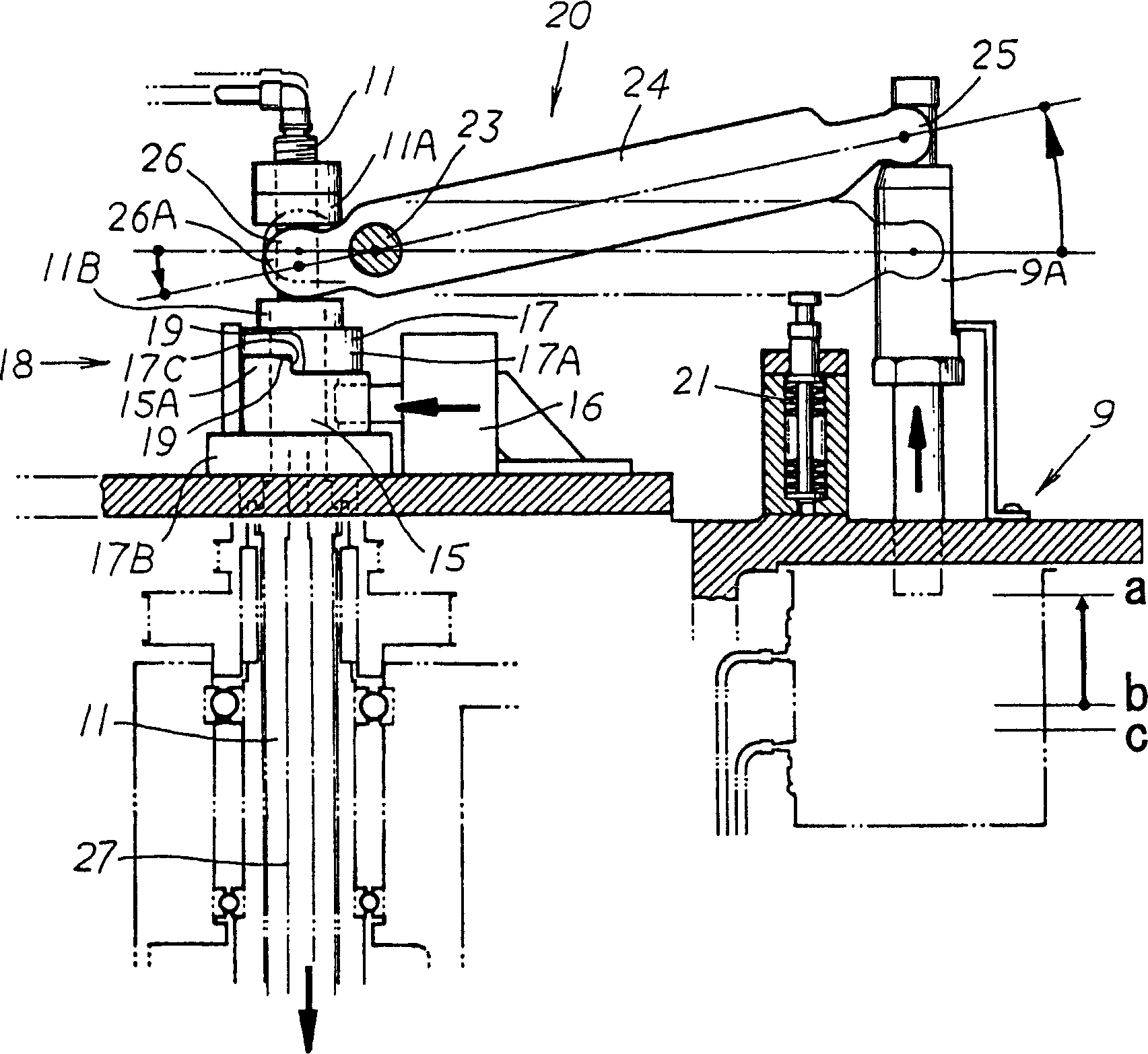
[0043] In addition, when the clamping mechanism 8 is released, the pull rod 7 is returned by the push of the advancing and retreating driving part 11 , so that the tool 1 can be attached and detached.

[0044] Specifically, the cylinder device 9 of the clamping mechanism 8, which is the pull rod driving device 9, is changed from the released state a to the first clamped state b, thereby clamping and fixing the rotary tool 1A, but in this case, the pull rod 7 is changed from The release position returned by the forward and ba...


PUM


Abstract

Provided is a tool mounting device for a turning center that allows a rotating tool (1A) to be clamped / fixed using a shared clamp mechanism ( 8 ), and a turning tool ( 1 B) to be clamped / fixed in an engaged / locked state in a turning center. In the turning center configured with the shared clamp mechanism ( 8 ), a cylinder device ( 9 ) acting as a drawbar drive device ( 9 ) of the clamp mechanism ( 8 ) has a first clamp position (b) and second clamp position (c) in relation to a release position (a); a rotation allowance gap ( 14 ) is maintained between the stopper ( 12 ) and the bearing unit ( 13 ) in the first clamp position (b) to specifically clamp / fix the rotating tool ( 1A); the reciprocating driver ( 11 ) is driven by an amount equal to the rotation allowance gap ( 14 ) in the second clamp position (c); and when the bearing unit ( 13 ) and the stopper ( 12 ) are brought into contact and a load is imposed, the stopper ( 12 ) is supported / stopped by the bearing unit ( 13 ), and the reciprocating driver ( 11 ) is engaged / locked by the wedge mechanism ( 18 ) in the position of the return blocking state in which the return of the drawbar ( 7 ) is blocked.

Description

technical field [0001] The present invention relates to a tool installation device of a turning machining center, which can properly replace a rotating tool and a turning tool for milling and cutting (turning). Background technique [0002] In the turning machining center, the main shaft is provided rotatably with respect to the ram through the bearing part, and the main shaft is provided with a mounting engaging part for engaging with a tapered shank provided at the base end of the tool. (taper shank), and a clamping mechanism is provided on the main shaft, which clamps the clamping protrusion of the taper shank by pulling the draw bar, and the taper shank Draw it closer and engage it on the installation engaging part, so that any tool can be detachably installed and fixed on the main shaft. In addition, the clamping mechanism is set to perform clamping, The release action allows each tool to be properly loaded and unloaded through this common clamping mechanism. In the ca...

Claims


Application Information

Patent Timeline
Patent Type & Authority Applications(China)
IPC IPC(8): B23B31/117B23B29/04
CPCY10T82/2511Y10T408/953Y10T409/309464Y10T409/309408Y10T408/95B23B31/261
Inventor 中村多喜夫后藤昭博清水达雄植田孝
Owner OM MFG CO LTD
Why Eureka
Try Eureka