Intelligent automobile and railway

A smart car and railway technology, applied to motor vehicles, rail and road dual-purpose vehicles, transportation and packaging, etc., can solve the problems of reduced driving power and fuel consumption, increased driving safety distance, increased braking distance, etc., to achieve safety Effects of shortened braking distance, improved vehicle speed and safety, and increased traffic density

Inactive Publication Date: 2006-09-06
李孝龙
View PDF0 Cites 10 Cited by
  • Summary
  • Abstract
  • Description
  • Claims
  • Application Information

AI Technical Summary

Problems solved by technology

[0002] At present, all countries in the world hope to develop an energy-saving dual-purpose road and railway vehicle that can run flexibly on the road and quickly and safely on the railway. The structure is complex and difficult to be practically applied
The application date is "Automobile Railway" on March 19, 2006. Although the above-mentioned problems have been solved, it can be put into application in large quantities. The vehicles on the railway are completely driven by steel wheels. Due to the rolling resistance between the wheel and rail, it is much smaller than that of rubber wheels and rubber wheels. The rolling resistance between the road surfaces, the driving power and fuel consumption of the vehicle are greatly reduced by nearly 70%. The efficiency of railway operations, while the speed is also restricted

Method used


Image

  • Intelligent automobile and railway
  • Intelligent automobile and railway
  • Intelligent automobile and railway

Examples


Embodiment 1

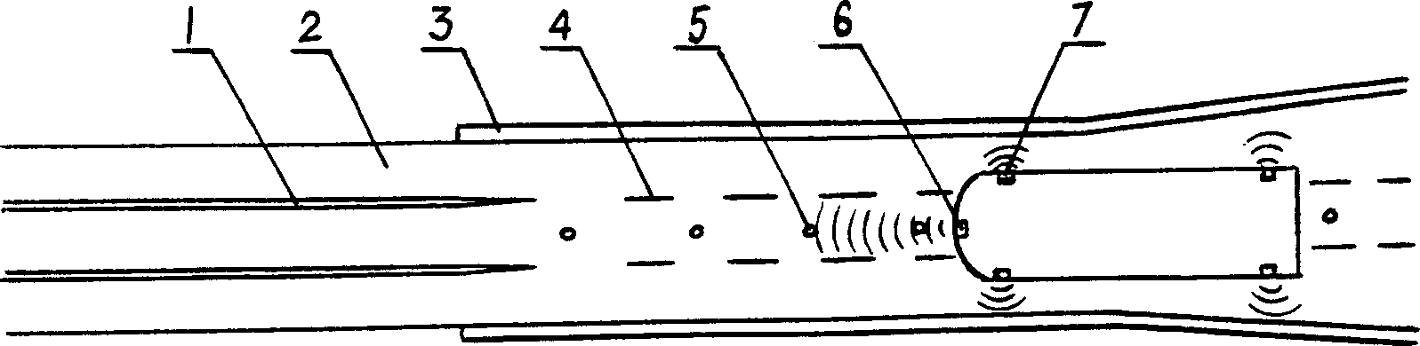
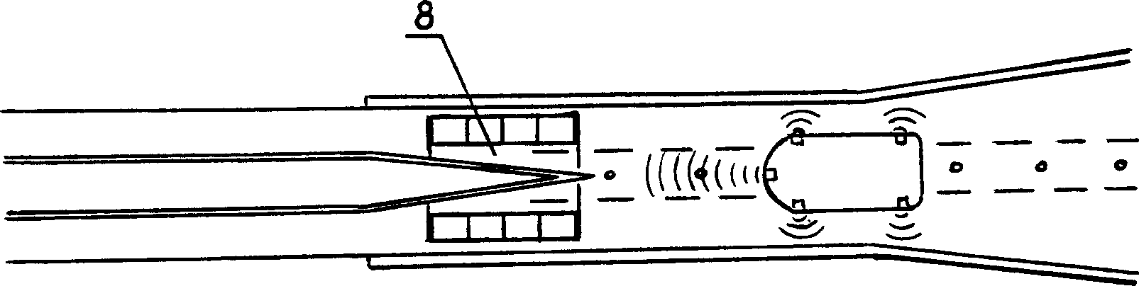
[0033] figure 1 As shown in , the rail 1 in the line is laid on the road surface 2 where the rubber wheels run, the guiding road section is located at the front end of the line, the guiding wall 3 is set on both sides, the guiding marking line 4 and the guiding magnetic nail 5 are set on the road surface, and the vehicle is guided into the road by the guiding wall. To guide the road section, the vehicle-mounted left and right distance sensors 7 measure the guide wall to determine the lateral position of the vehicle in the road section; The lateral relative position of the vehicle in the guiding road section, through the steering control device installed on the vehicle steering system, controls the steering wheel, so that the vehicle travels on the center line of the guiding road section, ensuring that the vehicle is aligned with the line and the steel wheel smoothly drives onto the rail; The vehicle is guided by steel wheels and driven by rubber wheels, both of which jointly c...

Embodiment 2

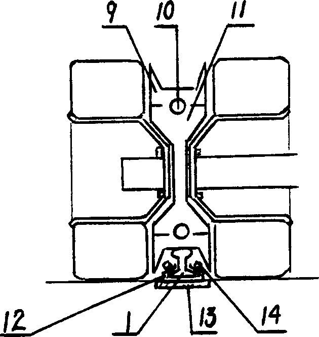
[0038] figure 2 As shown in , the steel wheel 9 is installed on the wheel core 11 through the axle disc 10, and the wheel core 11 is located between two rubber wheels or is installed on one side of the steel ring of the rubber wheel (see diagram 2-1 ), the rubber wheel runs on the road surface in the line, and the steel wheel runs on the top of the steel rail laid on the road surface; 14 adjustment fixed. The weight of the vehicle is carried by the steel wheel and the rubber wheel at the same time, and is driven by the steel wheel guiding the rubber wheel.

[0039] Figure 3 and Figure 4 As shown, the steel wheel 9 is installed below the chassis of the compartment or the frame of a large vehicle (see Pic 4-1 ), run on the rails laid above the track slab 15, and run on the rubber wheels on the road to jointly carry the weight of the vehicle. In the application, the small car line can be laid separately (see Fig. 3), also can unify steel wheel track and gauge with large c...

Embodiment 3

[0042] see Figure 6 , in the application, a hydraulic device can be installed on the steel wheel to adjust the pressure between the steel wheel and the rail, thereby adjusting the weight of the vehicle carried by the steel wheel, so that the weight of the vehicle carried between the steel wheel and the rubber wheel can be adjusted according to The operating status of the vehicle is assigned. As shown in the figure, the steel wheel 9 is located in the slide frame 20, the slide frame 20 is installed on the guide rod 19 in the wheel frame 18 through the axle sleeves at its two ends, and the push plate 23 installed on the guide rod 19 through the slide sleeve is positioned on the slide frame. Frame 20 tops, hydraulic cylinder 22 is established between the two, and air spring 21 is established between push plate 23 and the wheel frame 18 above, and return spring 21 is established under slide frame 20 and guide rod 19 simultaneously. When the vehicle starts and accelerates, the hy...


PUM


Abstract

The invention provides an intelligent vehicle used on special vehicle railway, with automatic driving property. It is characterized in that: the weight of vehicle is supported by the steel wheels and rubber wheels, while the steel wheels guide the direction and rubber wheels drive the vehicle, and the hydraulic device can adjust the weight. Since the rolling resistance of steel wheels is less than the rubber wheels, the oil consumption can be reduce 40-50%, with better starting, accelerating, and braking properties. And said special railway can be arranged on speedway and public transport line, with seamless connection between the railway and the road. The invention can reduce the transportation cost and protect the environment.

Description

technical field [0001] The invention relates to an intelligent car equipped with steel wheels and driven by rubber wheels for automatic cruising and driving on a special railway line, and a special line with steel rails laid on the road surface. Background technique [0002] At present, all countries in the world hope to develop an energy-saving dual-purpose road and railway vehicle that can run flexibly on the road and quickly and safely on the railway. The structure is complex and difficult to be practically applied. The application date is "Automobile Railway" on March 19, 2006. Although the above-mentioned problems have been solved, it can be put into application in large quantities. The vehicles on the railway are completely driven by steel wheels. Due to the rolling resistance between the wheel and rail, it is much smaller than that of rubber wheels and rubber wheels. The rolling resistance between the road surfaces, the driving power and fuel ...

Claims


Application Information

Patent Timeline
Patent Type & Authority Applications(China)
IPC IPC(8): B60F1/00
Inventor 李孝龙
Owner 李孝龙
Why Eureka
Try Eureka